
Page 166 - Microtectonics
P. 166
5.6 · Microscopic Shear Sense Indicators in Mylonite 155
common than shear band type. It is possible that, at (×Video 11.10c). However, false shear bands with the re-
higher metamorphic grade, zones of recrystallised grains verse sense of slip also occur (Fig. 5.45). If these develop
separate fragments instead of fracture zones. in a setting where individual layers can be traced, there is
Although attempts have been made to use fragmented no problem, but if they occur in a foliation, they may be
porphyroclasts as shear sense markers (Simpson and confused with normal shear bands (Fig. 5.46). Forward
Schmid 1983), they are relatively unreliable. Interpreta- rolling of the host element produces common structures
tion is usually as shown in Fig. 5.44. The overall shape of known as flanking folds (×Video 11.10a,b,d; Passchier
the aggregate is commonly that of a sigmoid, and this 2001; Graseman and Stüwe 2001; Graseman et al. 2003;
overall shape, together with the inferred domino or shear Exner et al. 2004; Wiesmayr and Grasemann 2005). Flank-
band type of the fracture system can be used to deter- ing folds can combine with reverse, normal or no slip
mine the shear sense. (×Video 11.10a–d). In all cases, the geometry of these
structures changes laterally along the crosscutting ele-
Flanking Structures ment, and dies out into the wall rock where the crosscut-
ting element ends (Fig. 5.45; ×Video 11.10a–d).
In many mylonite zones, oblique veins or faults transect Shear bands are straightforward in their interpre-
the mylonitic foliation or layering. Where such veins or tation as discussed above (Sect. 5.6.3) but false shear
faults (here referred to as crosscutting elements (CE); bands and flanking folds are not. Different mechanisms
Passchier 2001; Coelho et al. 2005) show evidence that can develop structures of similar or slightly different
they were intruded or active during mylonite generation, geometry, and the use of flanking folds or false shear
their interrelationship with a foliation or other host ele- bands as shear sense indicators is therefore only pos-
ment (HE) can give asymmetric structures that can oc- sible if the exact evolution of the structure can be re-
casionally be used as shear sense indicators. Shear band constructed (Graseman et al. 2003; Exner et al. 2004).
cleavage discussed in Sect. 5.6.3 is one example, but many Two major mechanisms can cause combinations of slip,
other geometries have been observed known as flanking lift, and rolling on crosscutting elements; (1) active slip
structures (Fig. 5.45). Critical elements of such structures along a fault in a ductile shear zone (×Video 11.10a–c),
are slip and lift of the host element with increasing dis- or presence of a planar competent body such as a vein
tance from the crosscutting element (Coelho et al. 2005; (×Video 11.10d) creates a deviating flow type close to
Fig. 5.45; ×Video 11.10a–d). Many combinations are pos- the fault which changes the geometry of the host element;
sible. In shear bands, normal slip can be accompanied by (2) infiltration of fluids from a vein changes the rheol-
non-rotation or back-rotation of the crosscutting element ogy of the adjacent host rock and further deformation
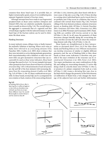
Fig. 5.47.
a Flanking fold without slip in
layering that is deflected against
a vein with an alteration zone
(dotted) can form in at least
three different ways: by coaxial
flattening b, by dextral shear c
and by sinistral shear d