
Page 168 - Microtectonics
P. 168
5.7 · Shear Sense Indicators in the Brittle Regime 157
5.7 5.7
Shear Sense Indicators in the Brittle Regime
5.7.1
Introduction
The internal fabric of gouge, cataclasite or breccia may
contain microstructures that can be used to determine
shear sense, as in mylonites. A problem in gouges and
cataclasites is that with some exceptions (Tanaka 1992),
penetrative lineations that could be used to determine
the movement direction are lacking. Instead, slickensides
(polished fault surfaces) occur that may contain parallel
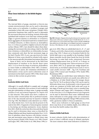
ridges or grooves (known as slickenlines or striations), Fig. 5.50. Schematic diagram showing the characteristic geometry and
shear sense of the most common types of Riedel shears (R-, R'-, P-, Y-
linear aggregates of cataclased material as isolated lenses and T-shears) in a brittle fault zone. Shear sense is mostly established
or behind obstacles, or fibres (known as slickenfibres; from deflection of older shears or, in foliated cataclasite or gouge, de-
Sect. 6.2.5) that are parallel or slightly inclined to the fault flection of the foliation (S). Mff – microscopic feather fractures
surface (Means 1987). Care should be taken when deter-
mining the movement direction along a fault in the field gan et al. 1992). They are subdivided into R-, R'-, P- and
from striations or slickenfibres on slickensides, because Y-shears, each with a characteristic orientation and shear
they commonly only show the last movement stage on sense (Fig. 5.50). Y-shears act as boundary faults for the
the fault (Tanaka 1992). In any case, specimens for estab- brittle fault zone or are parallel to the boundary. Riedel
lishment of shear sense should be oriented with respect shears resemble ductile shear bands but form by brittle
to the macroscopically determined movement direction. fracturing. In some fault rocks, extensional fractures
Sense of shear can be determined in the field from without displacement form at 20–50° to Y-shears or
displacement of markers as for ductile shear zones boundaries of the gouge zone. These are known as T-frac-
(Sect. 5.5.2) or from the shape of striations, slickenfibres tures (Petit 1987) or, if opened into wedge-shaped ten-
or minor faults on slickensides (Petit 1987). If slicken- sional veins, as microfault induced microcracks or micro-
fibres consist of calcite, the orientation distribution of scopic feather fractures (Mff – Fig. 5.50; Friedman and
deformation e-twins can be used to determine sense of Logan 1970; Conrad and Friedman 1976; Teufel 1981;
movement on the fault (Laurent 1987). Other shear sense Blenkinsop 2000).
criteria in thin section are given below. Riedel shears are useful shear sense indicators. Since
suitable displaced markers are usually rare, deflection of
5.7.2 a foliation or of older Riedel shears by younger shears
Incohesive Brittle Fault Rocks (e.g. P by R; Y by R as shown in Fig. 5.50) can be used to
determine shear sense. Synkinematic veins of quartz and
Although it is usually difficult to sample and cut gouge calcite are common in brittle fault rocks and occur in
or incohesive cataclasite, thin sections of such materials any stage of break-up from intact veins to rounded frag-
may give information on shear sense. A gouge normally ments (Chester and Logan 1987). Orientation of fibres
consists of rock and mineral fragments in a matrix rich in the veins (Sect. 6.2) or displacement of vein fragments
in clay minerals. This matrix may show a uniform ex- can be used to determine shear sense. Additional shear
tinction under crossed polars due to preferred orienta- sense indicators in some gouge zones are asymmetric
tion of the clay minerals and may be layered or foliated boudins and folds, sigmoids (Takagi 1998) and mica-fish,
(S in Fig. 5.50). The foliation is also referred to as a P-folia- with a geometry similar to those in mylonites.
tion. Shear bands (Sect. 5.6.3) may also be present in the Shear sense indicators in fault gouge as described
matrix (Lin 2001). Fragments of mineral grains resistant above may form at very shallow depth, even within me-
to fracturing can develop asymmetric strain shadows tres from the Earth’s surface (Lin 2001).
(Lin 2001). Both the extinction direction and shear bands
can be used to determine shear sense as described for 5.7.3
oblique foliation and shear bands in mylonite (Sect. 5.6.3). Cohesive Brittle Fault Rocks
Sets of subsidiary shear fractures with distinct orienta-
tion and movement sense, known as Riedel shears may In most cohesive brittle fault rocks determination of
also be present (Riedel 1929; Chester et al. 1985; Chester sense of shear is difficult, except in foliated cataclasite.
and Logan 1987, 1998; Rutter et al. 1986; Evans 1990; Lo- The most common shear sense indicators in foliated co-