
Page 47 - Microtectonics
P. 47
3.4 · Intracrystalline Deformation 35
The shape of a crystal cannot be permanently changed sources. An example is a Frank-Read source (Fig. 3.15b,
by just squeezing it; the distance between lattice points ×Video 3.15b).
can only be changed by a very small amount, leading to Ductile deformation of rocks is to a large extent
elastic deformation. If stress is released, the original achieved through the migration of dislocations and va-
shape is recovered. A permanent change in shape can cancies. Lattice defects can cause significant strain in crys-
only be achieved by a change in the relative positions of tals only if new defects are continuously created; this can
molecules or atoms. This happens by movement of lat- happen at dislocation sources and vacancy sources within
tice defects through a crystal in the process of intracrys- the crystal or at crystal boundaries.
talline deformation (Poirier 1985; Hull 1975). Intracrystalline deformation by glide of dislocations alone
Consider the vacancies in Fig. 3.12. If neighbour- is known as dislocation glide. Dislocations have a distinct
ing atoms occupy the vacancy sites, vacancies are orientation with respect to the crystal lattice and can move
moving through the crystal and the crystal may change only in specific crystallographic planes and directions
shape permanently (×Videos 3.12a, 3.12b). Moving (Fig. 3.11d). A specific slip plane coupled with a slip direc-
dislocations can also cause relative displacement of tion (the Burgers vector) is known as a slip system. Slip sys-
parts of a crystal lattice. Figure 3.15a (×Videos 3.11, tems (Box 3.4) for minerals are normally determined by TEM
3.15a) shows how movement of a dislocation dis- (Sect. 10.2.5; Fig. 10.11). In most common rock-forming min-
places parts of crystals without actually separating erals such as quartz, feldspars, calcite and olivine, several slip
one part of the crystal from the other. Dislocations systems of different orientation can be active (Sect. 3.12). The
can be generated in a crystal at so-called dislocation type of slip system that will be active in a crystal depends
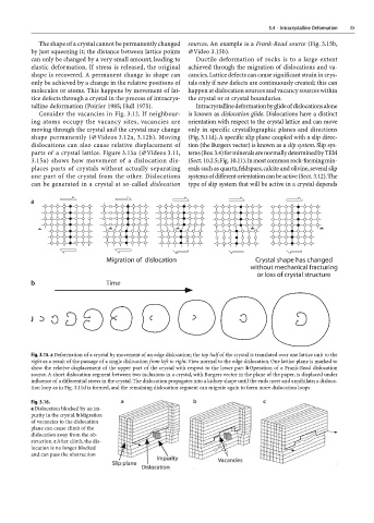
Fig. 3.15. a Deformation of a crystal by movement of an edge dislocation; the top half of the crystal is translated over one lattice unit to the
right as a result of the passage of a single dislocation from left to right. View normal to the edge dislocation. One lattice plane is marked to
show the relative displacement of the upper part of the crystal with respect to the lower part b Operation of a Frank-Read dislocation
source. A short dislocation segment between two inclusions in a crystal, with Burgers vector in the plane of the paper, is displaced under
influence of a differential stress in the crystal. The dislocation propagates into a kidney shape until the ends meet and annihilate; a disloca-
tion loop as in Fig. 3.11d is formed, and the remaining dislocation segment can migrate again to form more dislocation loops
Fig. 3.16.
a Dislocation blocked by an im-
purity in the crystal. b Migration
of vacancies to the dislocation
plane can cause climb of the
dislocation away from the ob-
struction. c After climb, the dis-
location is no longer blocked
and can pass the obstruction