Page 163 - Modern Control of DC-Based Power Systems
P. 163

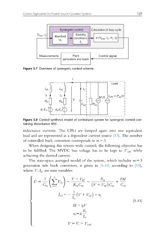
Control Approaches for Parallel Source Converter Systems     127


                                 Synergetic control  Calculation of duty cycle
                     V bus    n  Manifold  Stability
                        ; I
                                         conditions   d (V bus , I , Ψ , Ʒ )
                                                                i
                                                           n
                                                              i
                                 Ψ i
                                            Ʒ i
                      Measurements      Plant          Control signal
                                   generators and loads

              Figure 5.7 Overview of synergetic control scheme.

                                        I
                                                             Load
                                 L
                         L f1     fn          I C
                                 I
                          I 1     n                         I  = P /V
                                                       M (t)  CPL   eq
                                        V
                         R f1    R fn
                                             C eq  R eq
                       d ·E 1  d ·E n
                        1
                                n
              Figure 5.8 Control synthesis model of centralized system for synergetic control con-
              taining disturbance M(t).
              inductance currents. The CPLs are lumped again into one equivalent
              load and are represented as a dependent current source [13]. The number
              of controlled buck converters corresponds to m 5 3.
                 When designing this system-wide control, the following objective has
              to be fulfilled: The MVDC bus voltage has to be kept to V c;ref while
              achieving the desired current.
                 The state-space averaged model of the system, which includes m 5 3
              generation side buck converters, is given in (5.44) according to [15],
              where V; I Li are state variables:
                 8                 !
                              3
                         1                                        δM
                 >           X          V 1 V ref      P eq
                    _ V 5
                 >
                 >              V Li  2                         1
                 >                              2
                        C eq             R eq C eq  V 1 V ref C eq  C eq
                 >
                 >
                 >           i51
                 >
                 >
                 >
                 >
                                 I Li 52
                 >                       1
                 >               _
                 >                         V 1 V ref 1 u i
                 >
                                        L i
                 <
                                                                         (5.44)
                                         _ M 5 ηV
                 >
                 >
                 >
                 >
                 >
                 >
                 >                            E i
                 >
                 >                       u i 5d i
                 >
                                              L i
                 >
                 >
                 >
                 >
                 >
                 :
                                      V 5 V c 2 V c;ref
   158   159   160   161   162   163   164   165   166   167   168