
Page 263 - Modern Optical Engineering The Design of Optical Systems
P. 263
Optical Coatings 243
4%
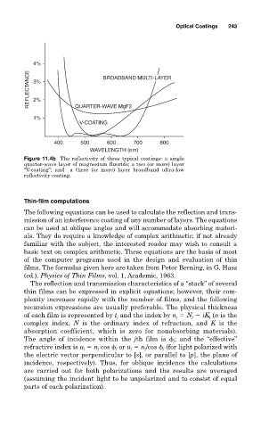
REFLECTANCE 3% BROADBAND MULTI-LAYER
2%
1% QUARTER-WAVE MgF2
V-COATING
400 500 600 700 800
WAVELENGTH (nm)
Figure 11.4b The reflectivity of three typical coatings: a single
quarter-wave layer of magnesium fluoride; a two (or more) layer
“V-coating”; and a three (or more) layer broadband ultra-low
reflectivity coating.
Thin-film computations
The following equations can be used to calculate the reflection and trans-
mission of an interference coating of any number of layers. The equations
can be used at oblique angles and will accommodate absorbing materi-
als. They do require a knowledge of complex arithmetic; if not already
familiar with the subject, the interested reader may wish to consult a
basic text on complex arithmetic. These equations are the basis of most
of the computer programs used in the design and evaluation of thin
films. The formulas given here are taken from Peter Berning, in G. Hass
(ed.), Physics of Thin Films, vol. 1, Academic, 1963.
The reflection and transmission characteristics of a “stack” of several
thin films can be expressed in explicit equations; however, their com-
plexity increases rapidly with the number of films, and the following
recursion expressions are usually preferable. The physical thickness
of each film is represented by t j and the index by n j N j iK j (n is the
complex index, N is the ordinary index of refraction, and K is the
absorption coefficient, which is zero for nonabsorbing materials).
The angle of incidence within the jth film is j ; and the “effective”
refractive index is u j n j cos j or u j n j /cos j (for light polarized with
the electric vector perpendicular to [s], or parallel to [p], the plane of
incidence, respectively). Thus, for oblique incidence the calculations
are carried out for both polarizations and the results are averaged
(assuming the incident light to be unpolarized and to consist of equal
parts of each polarization).