
Page 258 - Modern Optical Engineering The Design of Optical Systems
P. 258
238 Chapter Eleven
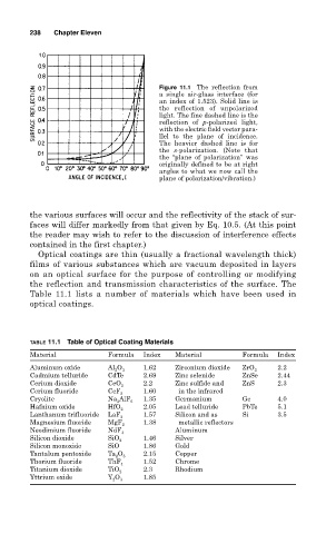
Figure 11.1 The reflection from
a single air-glass interface (for
an index of 1.523). Solid line is
the reflection of unpolarized
light. The fine dashed line is the
reflection of p-polarized light,
with the electric field vector para-
llel to the plane of incidence.
The heavier dashed line is for
the s-polarization. (Note that
the “plane of polarization” was
originally defined to be at right
angles to what we now call the
plane of polarization/vibration.)
the various surfaces will occur and the reflectivity of the stack of sur-
faces will differ markedly from that given by Eq. 10.5. (At this point
the reader may wish to refer to the discussion of interference effects
contained in the first chapter.)
Optical coatings are thin (usually a fractional wavelength thick)
films of various substances which are vacuum deposited in layers
on an optical surface for the purpose of controlling or modifying
the reflection and transmission characteristics of the surface. The
Table 11.1 lists a number of materials which have been used in
optical coatings.
TABLE 11.1 Table of Optical Coating Materials
Material Formula Index Material Formula Index
Aluminum oxide Al O 3 1.62 Zirconium dioxide ZrO 2 2.2
2
Cadmium telluride CdTe 2.69 Zinc selenide ZnSe 2.44
Cerium dioxide CeO 2 2.2 Zinc sulfide and ZnS 2.3
Cerium fluoride CeF 1.60 in the infrared
3
Cryolite Na AlF 6 1.35 Germanium Ge 4.0
3
Hafnium oxide HfO 2.05 Lead telluride PbTe 5.1
2
Lanthanum trifluoride LaF 3 1.57 Silicon and as Si 3.5
Magnesium fluoride MgF 1.38 metallic reflectors
2
Neodimium fluoride NdF 3 Aluminum
Silicon dioxide SiO 1.46 Silver
2
Silicon monoxide SiO 1.86 Gold
Tantalum pentoxide Ta O 2.15 Copper
2 5
Thorium fluoride ThF 4 1.52 Chrome
Titanium dioxide TiO 2.3 Rhodium
2
Yttrium oxide Y O 3 1.85
2