
Page 282 - Modern Optical Engineering The Design of Optical Systems
P. 282
262 Chapter Twelve
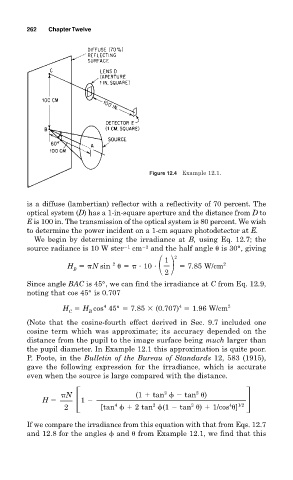
Figure 12.4 Example 12.1.
is a diffuse (lambertian) reflector with a reflectivity of 70 percent. The
optical system (D) has a 1-in-square aperture and the distance from D to
E is 100 in. The transmission of the optical system is 80 percent. We wish
to determine the power incident on a 1-cm square photodetector at E.
We begin by determining the irradiance at B, using Eq. 12.7; the
source radiance is 10 W ster 1 cm 2 and the half angle is 30°, giving
2
1
2
H N sin 10 7.85 W/cm 2
B
2
Since angle BAC is 45°, we can find the irradiance at C from Eq. 12.9,
noting that cos 45° is 0.707
4
4
H H cos 45° 7.85 (0.707) 1.96 W/cm 2
C B
(Note that the cosine-fourth effect derived in Sec. 9.7 included one
cosine term which was approximate; its accuracy depended on the
distance from the pupil to the image surface being much larger than
the pupil diameter. In Example 12.1 this approximation is quite poor.
P. Foote, in the Bulletin of the Bureau of Standards 12, 583 (1915),
gave the following expression for the irradiance, which is accurate
even when the source is large compared with the distance.
2
2
N (1 tan tan )
H 1
4
2
2
4
2 [tan 2 tan (1 tan ) 1/cos ] 1/2
If we compare the irradiance from this equation with that from Eqs. 12.7
and 12.8 for the angles and from Example 12.1, we find that this