
Page 277 - Modern Optical Engineering The Design of Optical Systems
P. 277
Principles of Radiometry and Photometry 257
with a radiance of N W ster 1 cm 2 and an intensity of J J 0 cos
NA cos W/ster. The incremental ring area on a hemisphere of radius R
has an area of 2 R sin R d and thus subtends (from A) a solid angle
2
2
of 2 R sin d /R 2 sin d steradians. The radiation intercepted
by this ring is the product of the intensity of the source and the solid
angle, or
dP J 2 sin d 2 NA sin cos d (12.3)
Integrating to find the total power radiated into the hemisphere from
A, we get
2
/2 sin /2
P
2 NA sin cos d 2 NA NA watts (12.4)
0 2 0
Dividing by A to get watts emitted per square centimeter of source,
we find the radiation into the 2 steradian of the hemisphere to be
N W/cm , not 2 N. This is the basic relationship between radiance and
2
the power emitted from the surface.
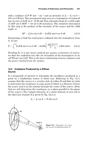
12.5 Irradiance Produced by a Diffuse
Source
It is frequently of interest to determine the irradiance produced at a
point by a lambertian source of finite size. Referring to Fig. 12.3,
assume that the source is a circular disk of radius R and that we wish
to determine the irradiance at some point X which is a distance S from
the source and is on the normal through the center of the source. (Note
that we will determine the irradiance on a plane parallel to the plane
of the source.) The radiant intensity of a small element of area dA in
the direction of point X is given by Eq. 12.2 as
J J cos N dA cos
0
Figure 12.3 Geometry of a circu-
lar source irradiating point X.