
Page 275 - Modern Optical Engineering The Design of Optical Systems
P. 275
Principles of Radiometry and Photometry 255
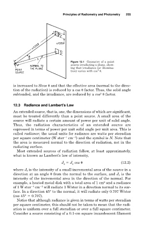
Figure 12.1 Geometry of a point
source irradiating a plane, show-
ing that irradiance (or illumina-
3
tion) varies with cos .
is increased to S/cos and that the effective area (normal to the direc-
tion of the radiation) is reduced by a cos factor. Thus, the solid angle
subtended, and the irradiance, are reduced by a cos factor.
3
12.3 Radiance and Lambert’s Law
An extended source, that is, one, the dimensions of which are significant,
must be treated differently than a point source. A small area of the
source will radiate a certain amount of power per unit of solid angle.
Thus, the radiation characteristics of an extended source are
expressed in terms of power per unit solid angle per unit area. This is
called radiance; the usual units for radiance are watts per steradian
per square centimeter (W ster 1 cm ) and the symbol is N. Note that
2
the area is measured normal to the direction of radiation, not in the
radiating surface.
Most extended sources of radiation follow, at least approximately,
what is known as Lambert’s law of intensity,
J J cos (12.2)
0
where J is the intensity of a small incremental area of the source in a
direction at an angle from the normal to the surface, and J 0 is the
intensity of the incremental area in the direction of the normal. For
2
example, a heated metal disk with a total area of 1 cm and a radiance
of 1 W ster 1 cm 2 will radiate 1 W/ster in a direction normal to its sur-
face. In a direction 45° to the normal, it will radiate only 0.707 W/ster
(cos 45° 0.707).
Notice that although radiance is given in terms of watts per steradian
per square centimeter, this should not be taken to mean that the radi-
ation is uniform over a full steradian or over a full square centimeter.
Consider a source consisting of a 0.1-cm square incandescent filament