
Page 346 - Modern Optical Engineering The Design of Optical Systems
P. 346
Optical System Layout 325
length equal to that of the prime lens f p in one direction and a focal
length equal to the magnification of the attachment times the prime lens
focal length Mf p in the other. In Fig. 13.26 the system is shown as a
reversed Galilean telescope with a magnification of less than unity,
and Mf p is less than f p . This is the type of system used in many wide-
screen motion picture processes. The wide angular field is used to
compress a large horizontal field of view into a normal film format.
The distorted picture which results is expanded to normal proportions
by projecting the film through a projection lens equipped with a similar
attachment. Note that these attachments are used with ordinary camera
and projector equipment.
Note that because an anamorphic system has a different equivalent
focal length in each meridian, if it is to be focused at a finite distance,
it will require a different shift of the lens to focus in each meridian. Thus
the prime (spherical) lens must be focused separately from the cylindri-
cal attachment (which is then focused by changing the space between
the two components). This type of focusing has the unfortunate effect of
changing the anamorphic ratio in a way which makes the face in a closeup
appear fatter than it actually is. This is not a popular effect among the
acting profession. There are two alternatives to this. One is to put a
focusing component in front of the system. This is usually a pair of weak
spherical elements, one positive and one negative, so that when closely
spaced their power is zero; as the spacing between them is increased,
their power becomes positive and the system is focused on a close dis-
tance. This is, in effect, a collimator for the object. The other alternative
is called a Stokes lens, which consists of a pair of weak cylinders of
equal but opposite powers, placed between the two components of the
afocal cylindrical attachment, with their axes tilted at 45° to the axes of
the attachment. When the two Stokes cylinders are counterrotated, both
meridians of the system are focused at the same time.
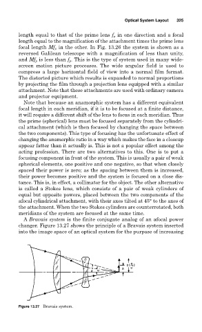
A Bravais system is the finite conjugate analog of an afocal power
changer. Figure 13.27 shows the principle of a Bravais system inserted
into the image space of an optical system for the purpose of increasing
Figure 13.27 Bravais system.