
Page 30 - Modular design for machine tools
P. 30
4 Modular Design Guide and Machine Tools Description
Cutting edge module
Shank module
Adapter module
Assembly diagram
Cutting edge module
Shank module
Clamping force
In release On work
Clamping mechanism of cutting edge to shank modules
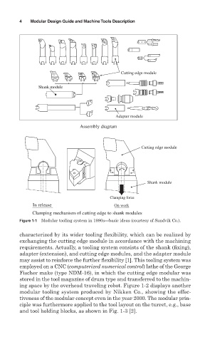
Figure 1-1 Modular tooling system in 1980s—basic ideas (courtesy of Sandvik Co.).
characterized by its wider tooling flexibility, which can be realized by
exchanging the cutting edge module in accordance with the machining
requirements. Actually, a tooling system consists of the shank (fixing),
adapter (extension), and cutting edge modules, and the adapter module
may assist to reinforce the further flexibility [1]. This tooling system was
employed on a CNC (computerized numerical control) lathe of the George
Fischer make (type NDM-16), in which the cutting edge modular was
stored in the tool magazine of drum type and transferred to the machin-
ing space by the overhead traveling robot. Figure 1-2 displays another
modular tooling system produced by Nikken Co., showing the effec-
tiveness of the modular concept even in the year 2000. The modular prin-
ciple was furthermore applied to the tool layout on the turret, e.g., base
and tool holding blocks, as shown in Fig. 1-3 [2].