
Page 191 - Multidimensional Chromatography
P. 191
184 Multidimensional Chromatography
n
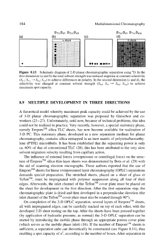
Figure 8.13 Schematic diagram of 2-D planar chromatographic separation using D. In the
first dimension (a and b) the total solvent strength was reduced stepwise at constant selectivity
(S T1 ; S V1 : S Tn ; S V1 ) to achieve differences in polarity. In the second dimension (c and d), the
selectivity was changed at constant solvent strength (S Tn ; S V1 : S Tn ; S Vm ) to achieve
maximum spot capacity.
8.9 MULTIPLE DEVELOPMENT IN THREE DIRECTIONS
A theoretical model whereby maximum peak capacity could be achieved by the use
of 3-D planar chromatographic separation was proposed by Guiochon and co-
workers (23–27). Unfortunately, until now, because of technical problems, this idea
could not be realized in practice. Very recently, however, a special stationary phase,
namely Empore TM silica TLC sheets, has now become available for realization of
3-D PC. This stationary phase, developed as a new separation medium for planar
chromatography, contains silica entrapped in an inert matrix of polytetrafluoroethy-
lene (PTFE) microfibrils. It has been established that the separating power is only
ca. 60% of that of conventional TLC (28); this has been attributed to the very slow
solvent migration velocity resulting from capillary action.
The influence of external forces (overpressure or centrifugal force) on the struc-
ture of Empore TM silica thin-layer sheets was demonstrated by Botz et al. (29) with
the aid of scanning electron micrographs. These authors reported that the use of
Empore TM sheets for linear overpressured layer chromatography (OPLC) separations
demands special preparation. The stretched sheets, placed on a sheet of glass or
TM
Teflon , must be impregnated with polymer suspension along all four of their
edges. Afterwards, the inlet channel of the Teflon TM cover plate must be placed on
the sheet for development in the first direction. After the first separation step, the
chromatographic plate is dried and then developed in a perpendicular direction (the
inlet channel of the Teflon TM cover plate must also be rotated through 90º).
On completion of the 2-D OPLC separation, several layers of Empore TM sheets,
all with impregnated edges, can be carefully stacked on top of each other, with the
developed 2-D sheet resting on the top. After the sheets have been pressed together
(by application of hydraulic pressure, as normal) the 3-D OPLC separation can be
started by introducing the mobile phase through an appropriate porous cover plate
(which serves as the mobile phase inlet) (16). If the number of Empore TM sheets is
sufficient, a separation cube can theoretically be constructed (see Figure 8.14), thus
3
enabling a spot capacity of n , according to the number of boxes. After separation in