
Page 370 - Numerical Analysis and Modelling in Geomechanics
P. 370
RESERVOIR COMPACTION, SUBSIDENCE AND WELL DAMAGE 351
failures at these depths involved mainly the shearing mode, although other
modes of failure in tension and compression have also occurred.
Field-scale model
The objective of the field-scale modeling was to develop relationships between
field operations and the global mechanisms that cause casing damage. The
results of the field-scale modeling are presented in this section.
Field-scale, two-dimensional, plane-strain finite element models developed for
this work were constructed from slices of a field-scale, three-dimensional, finite
element model developed during a simultaneous independent study of the South
Belridge field. 39,40 The three-dimensional finite element model was developed
from the grid system of a three-dimensional, finite-difference reservoir flow
model of Section 33. Two-dimensional slices of this finite difference grid were
oriented in roughly North-South and East-West directions. The North-South
oriented models capture the cross section of the field as shown in Figure 11.7,
while the East-West oriented models were aligned with the longitudinal axis of
the field. Only the North-South oriented model results are discussed in this
chapter.
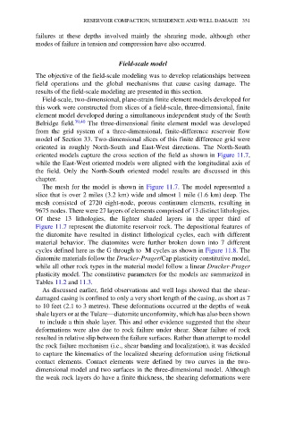
The mesh for the model is shown in Figure 11.7. The model represented a
slice that is over 2 miles (3.2 km) wide and almost 1 mile (1.6 km) deep. The
mesh consisted of 2720 eight-node, porous continuum elements, resulting in
9675 nodes. There were 27 layers of elements comprised of 13 distinct lithologies.
Of these 13 lithologies, the lighter shaded layers in the upper third of
Figure 11.7 represent the diatomite reservoir rock. The depositional features of
the diatomite have resulted in distinct lithological cycles, each with different
material behavior. The diatomites were further broken down into 7 different
cycles defined here as the G through to M cycles as shown in Figure 11.8. The
diatomite materials follow the Drucker-Prager/Cap plasticity constitutive model,
while all other rock types in the material model follow a linear Drucker-Prager
plasticity model. The constitutive parameters for the models are summarized in
Tables 11.2 and 11.3.
As discussed earlier, field observations and well logs showed that the shear-
damaged casing is confined to only a very short length of the casing, as short as 7
to 10 feet (2.1 to 3 metres). These deformations occurred at the depths of weak
shale layers or at the Tulare—diatomite unconformity, which has also been shown
to include a thin shale layer. This and other evidence suggested that the shear
deformations were also due to rock failure under shear. Shear failure of rock
resulted in relative slip between the failure surfaces. Rather than attempt to model
the rock failure mechanism (i.e., shear banding and localization), it was decided
to capture the kinematics of the localized shearing deformation using frictional
contact elements. Contact elements were defined by two curves in the two-
dimensional model and two surfaces in the three-dimensional model. Although
the weak rock layers do have a finite thickness, the shearing deformations were