
Page 97 - Numerical Analysis and Modelling in Geomechanics
P. 97
78 D.S.JENG
higher and will ultimately rely on the water depth, d. With an increase in the
burial depth there is a substantial reduction in the pore pressure.
Compared with coarse sand, it can be seen that there is a larger range of pore
pressure (p/p ) in fine sand (Figure 3.9(b)). The pore pressure around the pipeline
o
is less than in coarse sand, especially around the lower extent of the pipe. There
is a definite trend, as seen in each of the cases in Figure 3.9. The greater the
burial depth (b) of the pipeline, the smaller the pore pressure present around the
pipeline. However, it would be a very costly exercise if the pipe was to be
positioned deep within the seabed. The standard installation of underwater
pipelines is very costly to begin with, and to increase further the burial depth will
only add to the cost. There will thus need to be a compromise between the burial
depth and the allowable pore pressure. It should also be noted that the greater the
burial depth, the greater the subsequent overburden pressure. Thus careful
consideration must be given before commitment to the final design.
Pipe radius (R) is another important factor that directly affects the distribution
of the wave-induced seabed response. The distribution of the wave-induced pore
pressure around the pipe for various pipe radii is illustrated in Figure 3.10. The
figure indicates that the pipe radius only slightly affects the top portion of the
pipeline. However, with rotation around the pipeline to the lower extent there is a
significant reduction in the pore pressure (p/p ) with an increase in the pipe radius.
o
As a result the pore pressure is very similar on the top portion of the pipeline at
θ=90°. The increasing reduction in pore pressure results because at each
successive point around the pipeline with an increasing radius, it is situated
deeper within the seabed. The reduction in pore pressure is most noticeable in the
fine sand, as shown in Figure 3.10(b).
Effects of cover layer
It is well known that buried pipelines are damaged by wave-induced seabed
instability (such as liquefaction and scour). The wave pressure at the surface of
the seabed will push soil particles upward under wave troughs, while it pushes soil
particles downward under wave crests. This is the reason why liquefaction
occurs near wave troughs, and densification occurs near wave crests. Along with
the vertical soil movement, there can also be horizontal movement, which is a
result of the soil failing in shear. This occurs with the forward thrust of the
waves. By installing a coarser and more permeable material around the pipe, it is
expected to protect the seabed from scouring which will ultimately lead to the
failure of the pipeline.
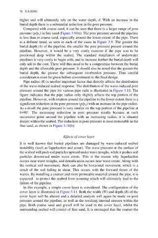
In this example, a simple cover layer is considered. The configuration of the
cover layer is illustrated in Figure 3.11. Both the width (W) and depth (B) of the
cover layer will be altered and a detailed analysis will again be made on pore
pressure around the pipeline, as well as the resulting internal stresses within the
pipe. Both coarse sand and gravel will be used in the cover layer, whilst the
surrounding seabed will consist of fine sand. It is envisaged that the coarser the