
Page 111 - Offshore Electrical Engineering Manual
P. 111
98 CHAPTER 8 Electric Cables
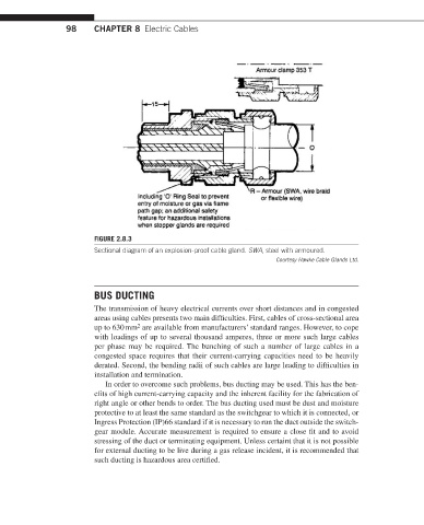
FIGURE 2.8.3
Sectional diagram of an explosion-proof cable gland. SWA, steel with armoured.
Courtesy Hawke Cable Glands Ltd.
BUS DUCTING
The transmission of heavy electrical currents over short distances and in congested
areas using cables presents two main difficulties. First, cables of cross-sectional area
2
up to 630 mm are available from manufacturers’ standard ranges. However, to cope
with loadings of up to several thousand amperes, three or more such large cables
per phase may be required. The bunching of such a number of large cables in a
congested space requires that their current-carrying capacities need to be heavily
derated. Second, the bending radii of such cables are large leading to difficulties in
installation and termination.
In order to overcome such problems, bus ducting may be used. This has the ben-
efits of high current-carrying capacity and the inherent facility for the fabrication of
right angle or other bends to order. The bus ducting used must be dust and moisture
protective to at least the same standard as the switchgear to which it is connected, or
Ingress Protection (IP)66 standard if it is necessary to run the duct outside the switch-
gear module. Accurate measurement is required to ensure a close fit and to avoid
stressing of the duct or terminating equipment. Unless certaint that it is not possible
for external ducting to be live during a gas release incident, it is recommended that
such ducting is hazardous area certified.