
Page 127 - Offshore Electrical Engineering Manual
P. 127
114 CHAPTER 11 Power Electronics (Semiconductor Equipment)
Provided the platform generated frequency and voltage are reasonably stable and
within a few percent of the nominal values, the inverter will normally remain in syn-
chronism with the generated supply. During generated voltage or frequency excur-
sions, the inverter will isolate itself from the main supply and continue to feed the
load by itself. A mains bypass supply is also available and, if the inverter fails, it is
automatically connected to the load. However, in some designs, if the bypass supply
is outside the inverter voltage or frequency tolerance, it will not be made available
to the load. This can be a problem if the generated supply is being obtained from the
emergency generator, which will not normally have such good voltage or frequency
holding capabilities as the larger machines.
It should be remembered that the inverter itself is generating a sine wave from
a power oscillator and therefore cannot produce a fault current much greater than
its rated current. For example, a 20-A inverter with the bypass supply unavailable
is able, at best, to blow a 6 A fuse in a reasonable time. If the distribution system
requires larger fuses, then an inverter of higher rating will normally be required. It
will not be necessary to provide a larger battery, however.
SELECTION OF VOLTAGE TOLERANCES
The general rule for establishing voltage tolerances is to optimise these for the mini-
mum output cable cross-sectional area and battery size. Having been provided with
or having calculated the diversified load current, discharge duration and voltage tol-
erances required for the equipment being supplied, the engineer can establish the
minimum battery size from the manufacturer’s tables.
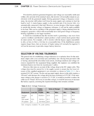
However, this takes no account of the voltage drop in the DC output cable. This
voltage drop must be catered for in the supply system to ensure that the lower tol-
erance of the supplied equipment is not exceeded, as shown in Table 2.11.1, for a
nominal 24 V DC system. The fire and gas panel supply shown in the table requires a
150-mm cable because the voltage drop has been restricted to 0.5 V DC. If the mini-
2
mum voltage at the charger is raised to 23.1 V DC, it would be possible to reduce the
2
cable size to 70 mm . However, to raise this voltage, it would be necessary to increase
the battery capacity, assuming the required discharge time remains constant.
Table 2.11.1 Voltage Tolerances
Cable Volts at Charger Volts at Equipment
2
(mm /
Equipment Load (A) length) Min. Max. Min. Max.
Fire/gas 40 150/50 m 22.5 26.4 22.0 26.4
panel
ESD panel 12.5 35/45 m 23.1 27.0 22.5 26.9
PA system 25 95/100 m 22.6 26.4 21.6 26.4
ESD, emergency shutdown; PA, public address.