
Page 151 - Offshore Electrical Engineering Manual
P. 151
138 CHAPTER 13 Subsea Supplies and Cathodic Protection
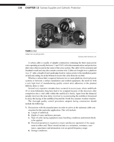
FIGURE 2.13.2
Inductive coupling units.
Courtesy Aker Solutions Ltd.
A subsea cable is usually of simpler construction containing the three main power
cores operating at usually between 11 and 33 kV, with telecommunications and protection
pilot wires often located in the centre of the cross-section. The cable will be armoured and
sheathed overall and may also contain a tension wire. Cables are brought on to a platform
via a ‘J’- tube, a length of steel guide pipe fixed at various points to the installation jacket
or hull and curling out at the bottom to receive the cable from the sea bed.
Whether a subsea link is required between two or more platform electrical power
systems or between a surface installation and seabed equipment, the need for both
a very high level of manufacturing quality control strict adherence to the planned
delivery dates is vital.
Several very expensive mistakes have occurred in recent years, where umbilicals
10 or more kilometres long have had to be scrapped because of the discovery after
completion that a vital cable within the umbilical is faulty. Apart from the financial
penalty involved, the time delay involved in reconstructing the umbilical threatened
to delay the laying of the umbilical beyond the North Sea summer weather window.
The thorough quality control procedures adopted during construction should
include the following:
1. Discussions with the manufacturers in order to arrive at the optimum cable con-
struction for the particular application. This will include:
a. Length of umbilical.
b. Depth of water and hence pressure.
c. Type of cable laying equipment used, handling conditions and tension likely
to be applied.
d. Electrical parameters required to ensure satisfactory operation of the equip-
ment at either end. These should include as a minimum, resistance, reac-
tance, capacitance and attenuation over an agreed frequency range.
e. Storage conditions.