
Page 169 - Offshore Electrical Engineering Manual
P. 169
156 CHAPTER 14 Offshore Lighting
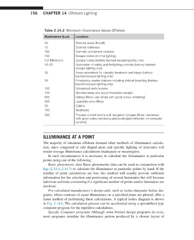
Table 2.14.2 Minimum Illuminance Values Offshore
Illuminance (Lux) Location
50 External areas (floodlit)
75 External walkways
100 Normally unmanned modules
100 Escape routes (normal lighting)
0.2 (Minimum) Escape routes (battery-backed escape lighting only)
10–30 Illumination of safety and firefighting controls (battery-backed
escape lighting only)
30 Areas earmarked for casualty treatment and triage (battery-
backed escape lighting only)
30 Emergency muster stations including lifeboat boarding (battery-
backed escape lighting only)
100 Unmanned switchrooms
100 Manned areas and accommodation except:-
500 Galleys [Note: use lamps with good colour rendering]
300 Laundries and offices
50 Cabins
150 Bedheads
300 Process control rooms and navigation bridges [Note: use lamps
with good colour rendering and avoid glare/reflection on computer
screens]
ILLUMINANCE AT A POINT
The majority of situations offshore demand other methods of illuminance calcula-
tion, since congested or odd shaped areas and specific lighting of structures will
render average illuminance calculations inadequate or meaningless.
In such circumstances it is necessary to calculate the illuminance at particular
points using one of the following:
Basic photometric data Basic photometric data can be used in conjunction with
Eqs (2.14.1–2.14.7) to calculate the illuminance at particular points by hand. If the
number of point calculations are few, this method will usually provide sufficient
information for the selection and positioning of several luminaires but will become
laborious and time-consuming if a significant number of points and/or luminaires are
involved.
Pre-calculated manufacturer’s design aids, such as isolux diagrams Isolux dia-
grams, where contours of equal illuminance on a specified plane are plotted, offer a
faster method of performing these calculations. A typical isolux diagram is shown
in Fig. 2.14.6. The calculation process can be accelerated using a spreadsheet type
computer program for the repetitive calculations.
Specific Computer programs Although some limited design programs do exist,
most programs simulate the illuminance pattern produced by a chosen layout of