
Page 32 - Offshore Electrical Engineering Manual
P. 32
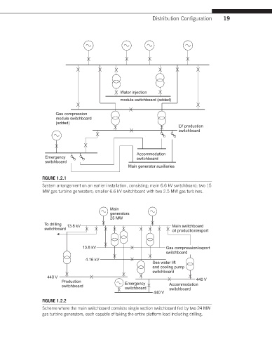
Distribution Configuration  19


                                                 Water injection
                                                 module switchboard (added)


                       Gas compression
                       module switchboard
                       (added)
                                                                        LV production
                                                                        switchboard


                                                       Accommodation
                   Emergency                           switchboard
                   switchboard
                                                    Main generator auxiliaries
                  FIGURE 1.2.1
                  System arrangement on an earlier installation, consisting; main 6.6 kV switchboard; two 15
                  MW gas turbine generators; smaller 6.6 kV switchboard with two 2.5 MW gas turbines.


                                             Main
                                             generators
                                             25 MW
                   To drilling  13.8 kV                              Main switchboard
                   switchboard                                       oil production/export


                                  13.8 kV                          Gas compression/export
                                                                   switchboard
                                   4.16 kV
                                                             Sea water lift
                                                             and cooling pump
                                                             switchboard
                    440 V                                                      440 V
                         Production                Emergency
                         switchboard                                Accommodation
                                                   switchboard      switchboard
                                                              440 V
                  FIGURE 1.2.2
                  Scheme where the main switchboard consists: single section switchboard fed by two 24 MW
                  gas turbine generators, each capable of taking the entire platform load including drilling.