Page 33 - Offshore Electrical Engineering Manual
P. 33

20     CHAPTER 2  The Offshore Electrical Environment


                                                  G1  G2      G3
                                                  5MVA  5MVA  5MVA
                                                  11kV  11kV  11kV
                                                28  G  G  29  30  G
                                                NER  1  2NER  NER  3
                                                 31     32    33
                                                   CB9          CB15  CB16
                               Section A              CB10
                               1.1 kV 3ph 800A 50 Hi 350MVA  CB13       Section B
                                                                                       Rear busbar
                                                      CB11  CB14
                                                                                       Front busbar
                                                         CB12
                                 CB3  CB4  CB5  CB6  CB7  CB8         CB18  CB19  CB20  CB21  CB22  CB23
                                       9  6  7  4                     5  8  10  11
                                              34  T1               T2
                                            5081                    35
                                             NER  5081             NER
                           T1 & T2 2MVA 85% AV  T3  36
                           T3,T4 * T5 3 5MVA6% AV  5080  T4              T5
                           T6, T7 & T8 1750kVA 11*AV  12              14
                                                                         5082
                                       NER  NER                       NER  5085
                                           5084
                                                                   CB83
                                     T6   16  17  CB61  Thyristor supplies CB62* 600V 3ph 250A 42MVA  18  T7  T8
                                       5083  CB32  CB34               CB36
                                       19       3.3kV 3ph 800A 150MVA CB35  20  21
                                       CB41  CB33  CB31               CB37  CB45  CB47  Production and
                                          415V 3ph 4 wire 3000A 35MVA  CB42*  CB46*  domestic services
                           MCC1      Production and             Essential  CB43*  CB44  CB48*  CB49*  MCC3
                                     domestic services
                             CB76* CB71*  CB58             CB57  services  22  25  24  23  CB72  CB77
                                   28                      27            1S51 1S52  1S53
                                   1S54 Drilling equipment  1355
                                                   Drilling equipment  MCC8  G  G8  G  G7
                                 MCC5                                  415 V      415
                             6064  509  C78            C79                           1377  8083
                                       1598            1677          CS0
                                       1S81            1S82
                                    MCCa  Rig ancillaries  MCC10  Rig ancillaries
                                   1S73  1S75        1S83  1S85                   *Denoles
                                    1S74              1S84                        circuit breaker
                                  MOL aux MCC7      NGL aux MCC*                  normally open
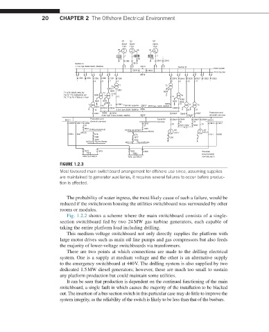
                         FIGURE 1.2.3
                         Most favoured main switchboard arrangement for offshore use since, assuming supplies
                         are maintained to generator auxiliaries, it requires several failures to occur before produc-
                         tion is affected.
                            The probability of water ingress, the most likely cause of such a failure, would be
                         reduced if the switchroom housing the utilities switchboard was surrounded by other
                         rooms or modules.
                            Fig. 1.2.2 shows a scheme where the main switchboard consists of a single-
                         section switchboard fed by two 24 MW gas turbine generators, each capable of
                         taking the entire platform load including drilling.
                            This medium-voltage switchboard not only directly supplies the platform with
                         large motor drives such as main oil line pumps and gas compressors but also feeds
                         the majority of lower-voltage switchboards via transformers.
                            There are two points at which connections are made to the drilling electrical
                         system. One is a supply at medium voltage and the other is an alternative supply
                         to the emergency switchboard at 440 V. The drilling system is also supplied by two
                         dedicated 1.5 MW diesel generators; however, these are much too small to sustain
                         any platform production but could maintain some utilities.
                            It can be seen that production is dependent on the continued functioning of the main
                         switchboard, a single fault in which causes the majority of the installation to be blacked
                         out. The insertion of a bus section switch in this particular case may do little to improve the
                         system integrity, as the reliability of the switch is likely to be less than that of the busbars.
   28   29   30   31   32   33   34   35   36   37   38