
Page 123 - Op Amps Design, Applications, and Troubleshooting
P. 123
106 AMPLIFIERS
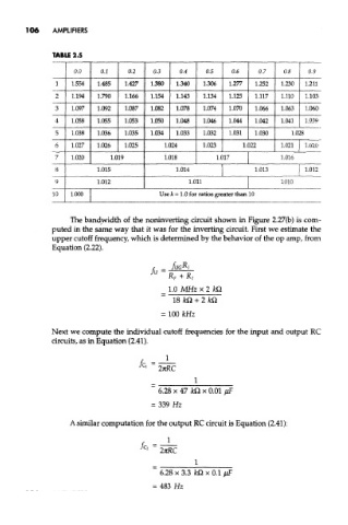
TABLE 2.5
0,0 0.1 0.2 0.3 0.4 0.5 0.6 0.7 0.8 0.9
1 1.554 1.485 1.427 1.380 1.340 1.306 1.277 1.252 1.230 1.211
2 1.194 1.790 1.166 1.154 1.143 1.134 1.125 1.117 1.110 1.103
3 1.097 1.092 1.087 1.082 1.078 1.074 1.070 1.066 1.063 1.060
4 1.058 1.055 1.053 1.050 1.048 1.046 1.044 1.042 1.041 1.039
5 1.038 1.036 1.035 1.034 1.033 1.032 1.031 1.030 1.028
6 1.027 1.026 1.025 1.024 1.023 1.022 1.021 1.020
7 1.020 1.019 1.018 1.017 1.016
8 1.015 1.014 1.013 1.012
9 1.012 1.011 1,010
10 1.000 Use k = 1.0 for ratios greater than 10
The bandwidth of the noninverting circuit shown in Figure 2.27(b) is com-
puted in the same way that it was for the inverting circuit. First we estimate the
upper cutoff frequency, which is determined by the behavior of the op amp, from
Equation (2.22).
Next we compute the individual cutoff frequencies for the input and output RC
circuits, as in Equation (2.41).
A similar computation for the output RC circuit is Equation (2.41):