
Page 128 - Op Amps Design, Applications, and Troubleshooting
P. 128
Current Amplifier 111
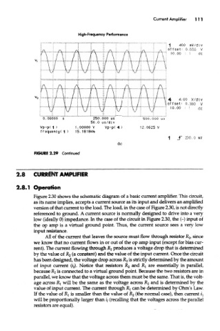
FIGURE 2.29 Continued
2.8 CURRENT AMPLIFIER
2.8.1 Operation
Figure 2.30 shows the schematic diagram of a basic current amplifier. This circuit,
as its name implies, accepts a current source as its input and delivers an amplified
version of that current to the load. The load, in the case of Figure 2.30, is not directly
referenced to ground. A current source is normally designed to drive into a very
low (ideally 0) impedance. In the case of the circuit in Figure 2.30, the (-) input of
the op amp is a virtual ground point. Thus, the current source sees a very low
input resistance.
All of the current that leaves the source must flow through resistor R 2, since
we know that no current flows in or out of the op amp input (except for bias cur-
rent). The current flowing through R 2 produces a voltage drop that is determined
by the value of R 2 (a constant) and the value of the input current. Once the circuit
has been designed, the voltage drop across R 2 is strictly determined by the amount
an( are
of input current (//). Notice that resistors R 2 i ^i essentially in parallel,
because R 2 is connected to a virtual ground point. Because the two resistors are in
parallel, we know that the voltage across them must be the same. That is, the volt-
age across Rj will be the same as the voltage across R 2 and is determined by the
value of input current. The current through RI can be determined by Ohm's Law.
If the value of R x is smaller than the value of R 2 (the normal case), men current z'j
will be proportionally larger than f/ (recalling that the voltages across the parallel
resistors are equal).