
Page 129 - Op Amps Design, Applications, and Troubleshooting
P. 129
112 AMPLIFIERS
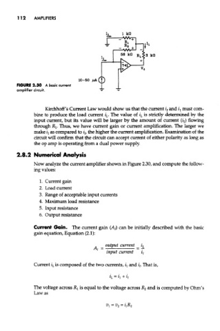
FIGURE 2.30 A basic current
amplifier circuit.
Kirchhoff's Current Law would show us that the current z"/ and *\ must com-
bine to produce the load current i L. The value of i L is strictly determined by the
input current, but its value will be larger by the amount of current (i^ flowing
through RI- Thus, we have current gain or current amplification. The larger we
make fj as compared to z/, the higher the current amplification. Examination of the
circuit will confirm that the circuit can accept current of either polarity as long as
the op amp is operating from a dual power supply.
2.8.2 Numerical Analysis
Now analyze the current amplifier shown in Figure 2.30, and compute the follow-
ing values:
1. Current gain
2. Load current
3. Range of acceptable input currents
4. Maximum load resistance
5. Input resistance
6. Output resistance
Current Gain. The current gain (A/) can be initially described with the basic
gain equation, Equation (2.1):
Current i L is composed of the two currents, ii and £/. That is,
The voltage across R l is equal to the voltage across R 2 and is computed by Ohm's
Law as