
Page 166 - Op Amps Design, Applications, and Troubleshooting
P. 166
Voltage Comparator with Hysteresis 149
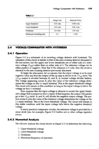
TABU 3.1
Design Goal Measured Values
Upper threshold -s-0.5 volts +0.54 volts
Lower threshold -0.5 volts -0.51 volts
Hysteresis 1.0 volts 1.05 volts
Maximum switching ratio 0.2 0.126
3.4 VOLTAGE COMPARATOR WITH HYSTERESIS
Figure 3.11 is a schematic of an inverting voltage detector with hysteresis. The
operation of this circuit is similar to that of the zero-crossing detector discussed in
the last section, but the upper and lower thresholds are on either side of a refer-
ence voltage (V REf) rather than on either side of 0. The reference voltage can be
either positive or negative. Note that if the reference is 0 volts, then the circuit is
identical to the zero-crossing detector previously discussed.
To begin the discussion, let us assume that the input voltage is at its most
negative value and that the output of the op amp is driven to its + VSAT level, The
+V SAT output is divided between R F and Rj in normal voltage divider fashion.
The voltage appearing across RI plus the value of the reference voltage deter-
mines the voltage on the {+) input terminal. This is the upper threshold voltage.
The circuit will remain in this condition as long as the input voltage is below the
voltage on the (+) terminal
Now suppose that the input voltage is allowed to exceed the upper thresh-
old voltage that is present on the (+) input. If this happens, the output will quickly
go to the -V$ AT level. R F and R l will divide the negative output voltage. The por-
tion across RI plus the value of the reference voltage determines the voltage on the
(+) input terminal. This is the lower threshold voltage. The circuit will remain in
this stable condition until the input voltage falls below the negative threshold
voltage.
In many practical comparator circuits, the reference voltage is provided by a
zener diode (see, for example, Figure 3.12 further on) or other voltage regulator
circuit.
3.4.2 Numerical Analysis
We will now analyze the circuit shown in Figure 3.11 to determine the following:
1. Upper threshold voltage
2. Lower threshold voltage
3. Hysteresis
4. Maximum frequency of operation