
Page 164 - Op Amps Design, Applications, and Troubleshooting
P. 164
Zero-Crossing Detector with Hysteresis 147
put swing will be approximately ±13 volts. We use this value for our computa-
tions. If the circuit is expected to drive a greater load (smaller load resistor), then
the output will be correspondingly smaller. The ratio of R F to R! is computed as
follows:
More specifically, for the present circuit we have
Many combinations of R F and R l will produce a 25:1 ratio. We will select R t
and calculate the value of R F. If possible, we generally want both resistors in the
range of 1.0 kilohm to 1.0 megohm, although these do not represent absolute lim-
its. For purposes of this example, we select R T to be 4.7 kilohms. Having done this,
we can now compute R F by simply multiplying R a by the R F/Ri ratio.
And, in the present case,
We will select a standard value of 120 kilohms.
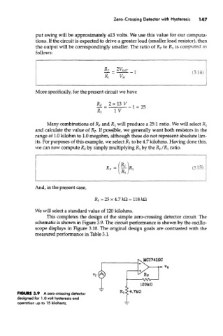
This completes the design of the simple zero-crossing detector circuit. The
schematic is shown in Figure 3.9. The circuit performance is shown by the oscillo-
scope displays in Figure 3.10. The original design goals are contrasted with the
measured performance in Table 3.1.
FIGURE 3.9 A zero-crossing detector
designed for 1.0 volt hysteresis and
operation up to 15 kilohertz.