
Page 159 - Op Amps Design, Applications, and Troubleshooting
P. 159
142 VOLTAGE COMPARATORS
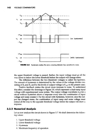
FIGURE 3.8 Hysteresis makes the zero-crossing detector less sensitive to noise.
the upper threshold voltage is passed. Rather, the input voltage must go all the
way down to below the lower threshold before the output will change states.
The difference between the two threshold voltages is called the hysteresis.
The amount of hysteresis is determined by the values of the voltage divider con-
sisting of R F and Rj and by the levels of output voltage (±V SAT in the present case).
Positive feedback makes the circuit more immune to noise. To understand
this effect, consider the drawings in Figure 3.8, which represent a dual-ramp input
voltage with superimposed noise pulses. The output voltage waveform (v 0) for a
circuit without hysteresis shows a response every time the combination of input
voltage and noise crosses 0. For the circuit with hysteresis, however, once the out-
put has changed states, the combination of input ramp and noise voltage must
extend all the way to the opposite threshold voltage before the output will show a
response.
3.3.2 Numerical Analysis
Let us now analyze the circuit shown in Figure 3.7. We shall determine the follow-
ing values:
1. Upper threshold voltage
2. Lower threshold voltage
3. Hysteresis
4. Maximum frequency of operation