
Page 158 - Op Amps Design, Applications, and Troubleshooting
P. 158
Zero-Crossing Detector with Hysteresis 141
3.3 ZERO-CROSSING DETECTOR WITH HYSTERESIS
3.3.1 Operation
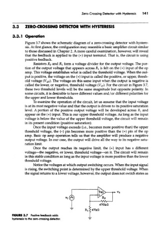
Figure 3.7 shows the schematic diagram of a zero-crossing detector with hystere-
sis. At first glance, the configuration may resemble a basic amplifier circuit similar
to those discussed in Chapter 2. A more careful examination, however, will reveal
that the feedback is applied to the (+) input terminal. That is, the circuit is using
positive feedback.
Resistors JR F and RI form a voltage divider for the output voltage. The por-
tion of the output voltage that appears across RI is felt on the (+) input of the op
amp. This voltage establishes what is called the threshold voltage. When the out-
put is positive, the voltage on the (+) input is called the positive, or upper, thresh-
old voltage (V UT). The voltage on this same input when the output is negative is
called the lower, or negative, threshold voltage (V LT). For the circuit in Figure 3.7,
these two threshold levels will be the same magnitude but opposite polarity. In
some circuits, it is desirable to have different values and/or different polarities for
the upper and lower thresholds.
To examine the operation of the circuit, let us assume that the input voltage
is at its most negative value and that the output is driven to its positive saturation
level. A portion of the positive output voltage will be developed across RI and
appear on the (+) input. This is our upper threshold voltage. As long as the input
voltage is below the value of the upper threshold voltage, the circuit will remain
in its present condition (positive saturation).
Once the input voltage exceeds (i.e., becomes more positive than) the upper
threshold voltage, the (-) pin becomes more positive than the (+) pin of the op
amp. Bask op amp operation tells us that the amplifier will produce a negative
output voltage. In our case, the output will drive all the way to its negative satu-
ration limit.
Once the output reaches its negative limit, the (+) input has a different
voltage—the negative, or lower, threshold voltage—on it. The circuit will remain
in this stable condition as long as the input voltage is more positive than the lower
threshold voltage.
Notice the voltages at which output switching occurs. When the input signal
is rising, the switching point is determined by the upper threshold voltage. When
the signal returns to a lower voltage, however, the output does not switch states as
FIGURE 3.7 Positive feedback adds
hysteresis to the zero-crossing detector.