
Page 153 - Op Amps Design, Applications, and Troubleshooting
P. 153
136 VOLTAGE COMPARATORS
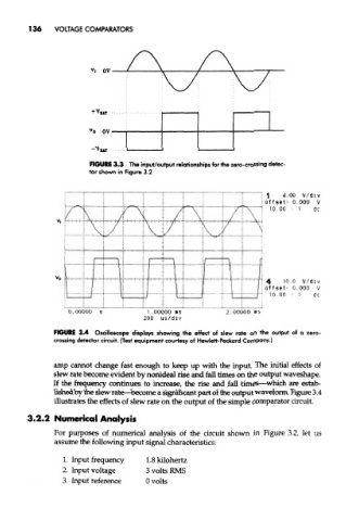
FIGURE 3.3 The input/output relationships for the zero-crossing detec-
tor shown in Figure 3.2
FIGURE 3.4 Oscilloscope displays showing the effect of slew rate on the output of a zero-
crossing detector circuit. (Test equipment courtesy of Hewlett-Packard Company.)
amp cannot change fast enough to keep up with the input. The initial effects of
slew rate become evident by nonideal rise and fall times on the output waveshape.
If the frequency continues to increase, the rise and fall times—which are estab-
lished by the slew rate—become a significant part of the output waveform. Figure 3,4
illustrates the effects of slew rate on the output of the simple comparator circuit.
3.2.2 Numerical Analysis
For purposes of numerical analysis of the circuit shown in Figure 3.2, let us
assume the following input signal characteristics:
1. Input frequency l.Skilohertz
2. Input voltage 3 volts RMS
3. Input reference 0 volts