
Page 156 - Op Amps Design, Applications, and Troubleshooting
P. 156
Zero-Crossing Detector 139
Our maximum rise and fall times will then be computed as
In the present case, we have
£ R(max) = f F(max) = 0.1 x 50 us = 5 fjs
The minimum acceptable slew rate for our op amp can be computed with the fol-
lowing equation:
In our present example, the minimum acceptable slew rate is computed as
6
It is common to divide this result by 10 and express the slew rate in terms of volts
per microsecond. In our case,
The slew rate for a 741 op amp is listed in the data sheet as 0.5 volts per
microsecond. Clearly, this is too slow for our application. If we use the 741, our
output signal will look more like a triangle wave than a square wave. Appendix 4
shows the data for another alternative.
The MCI741SC op amp should satisfy the voltage specifications of our
design. Additionally, the minimum slew rate is listed as 10 volts per microsecond.
We will use the MC1741SC for our design.
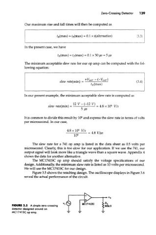
Figure 3.5 shows the resulting design. The oscilloscope displays in Figure 3.6
reveal the actual performance of the circuit.
FIGURE 3.5 A simple zero-crossing
detector designed around an
MCI74ISC op amp.