
Page 152 - Op Amps Design, Applications, and Troubleshooting
P. 152
Zero-Crossing Detector 135
FIGURE 3.1 The voltage comparator is often used in alarm appli-
cations. In this figure, the alarm sounds when the voltage from the
pressure sensor exceeds the voltage set by the potentiometer.
3.2 ZERO-CROSSING DETECTOR
3.2.1 Operation
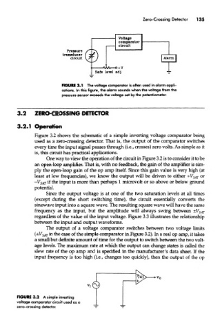
Figure 3.2 shows the schematic of a simple inverting voltage comparator being
used as a zero-crossing detector. That is, the output of the comparator switches
every time the input signal passes through (i.e., crosses) zero volts. As simple as it
is, this circuit has practical applications.
One way to view the operation of the circuit in Figure 3.2 is to consider it to be
an open-loop amplifier. That is, with no feedback, the gain of the amplifier is sim-
ply the open-loop gain of the op amp itself. Since this gain value is very high (at
least at low frequencies), we know the output will be driven to either +V SAT or
-V SAT if the input is more than perhaps 1 microvolt or so above or below ground
potential.
Since the output voltage is at one of the two saturation levels at all times
(except during the short switching time), the circuit essentially converts the
sinewave input into a square wave. The resulting square wave will have the same
frequency as the input, but the amplitude will always swing between ±V SAT
regardless of the value of the input voltage. Figure 3.3 illustrates the relationship
between the input and output waveforms.
The output of a voltage comparator switches between two voltage limits
(±V SAT in the case of the simple comparator in Figure 3.2). In a real op amp, it takes
a small but definite amount of time for the output to switch between the two volt-
age levels. The maximum rate at which the output can change states is called the
slew rate of the op amp and is specified in the manufacturer's data sheet. If the
input frequency is too high (i.e., changes too quickly), then the output of the op
741
-h
FIGURE 3.2 A simple inverting
voltage comparator circuit used as a
zero-crossing detector.