
Page 172 - Op Amps Design, Applications, and Troubleshooting
P. 172
Voltage Comparator with Hysteresis 155
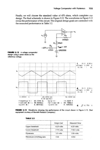
Finally, we will choose the standard value of 470 ohms, which completes our
design. The final schematic is shown in Figure 3.12. The waveforms in Figure 3.13
reveal the performance of the circuit. The original design goals are contrasted with
the measured performance in Table 3.2.
FIGURE 3.12 A voltage comparator
design using a zener diode as the
reference voltage.
FIGURE 3.13 Waveforms showing the performance of the circuit shown in Figure 3.12, (Test
equipment courtesy of Hewlett-Packard Company.)
TABLE 3.2
Design Goal Measured Value
Upper threshold -4,25 volts -4.25 volts
Lower threshold -7.75 volts -7.813 volts
Hysteresis 3.5 volts 3.56 volts
Maximum switching ratio 0.02 0.012