
Page 173 - Op Amps Design, Applications, and Troubleshooting
P. 173
1S6 VOLTAGE COMPARATORS
3.5 WINDOW VOLTAGE COMPARATOR
3.5.1 Operation
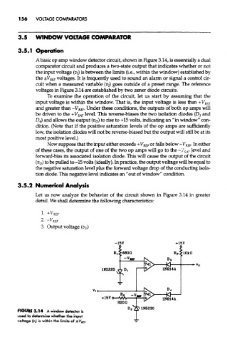
A basic op amp window detector circuit, shown in Figure 3.14, is essentially a dual
comparator circuit and produces a two-state output that indicates whether or not
the input voltage (p/) is between the limits (i.e., within the window) established by
the ±V R£ F voltages. It is frequently used to sound an alarm or signal a control cir-
cuit when a measured variable (vj) goes outside of a preset range. The reference
voltages in Figure 3.14 are established by two zener diode circuits.
To examine the operation of the circuit, let us start by assuming that the
input voltage is within the window. That is, the input voltage is less than +V REf
and greater than -V REF. Under these conditions, the outputs of both op amps will
be driven to the +V SAT level. This reverse-biases the two isolation diodes (D 3 and
D 4) and allows the output (v 0) to rise to +15 volts, indicating an "in window" con-
dition. (Note that if the positive saturation levels of the op amps are sufficiently
low, the isolation diodes will not be reverse-biased but the output will still be at its
most positive level.)
Now suppose that the input either exceeds + V REF or falls below -V REF. In either
of these cases, the output of one of the two op amps will go to the ~V SAT level and
forward-bias its associated isolation diode. This will cause the output of the circuit
(%) to be pulled to -15 volts (ideally). In practice, the output voltage will be equal to
the negative saturation level plus the forward voltage drop of the conducting isola-
tion diode. This negative level indicates an "out of window" condition.
3.5.2 Numerical Analysis
Let us now analyze the behavior of the circuit shown in Figure 3.14 in greater
detail. We shall determine the following characteristics:
FIGURE 3.14 A window detector is
used to determine whether the input
voltage (v,) is within the limits of ±V REF.