
Page 179 - Op Amps Design, Applications, and Troubleshooting
P. 179
162 VOLTAGE COMPARATORS
voltage on the (-) terminal. Note that because the rising output has increased the
potential on the (+) input, the actual input voltage (*>/) will have to go to a much
lower level to cause the circuit to switch states. This effect is, of course, the very
nature of hysteresis.
If the input voltage now decreases to a level that causes the voltage on the
(+) pin to fall below the voltage on the (-) pin, then the circuit will switch back to
its original state.
3.6.2 Numerical Analysis
Now let us extend our analysis of Figure 3.17 to calculate the following:
1. Upper threshold voltage
2. Lower threshold voltage
3. Hysteresis
4. All zener currents
+
5. Output voltage limits (v 0 and v 0~)
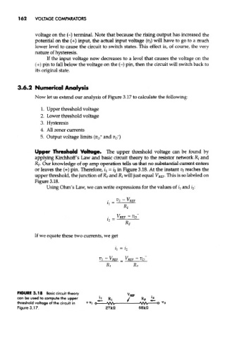
Upper Threshold Voltage. The upper threshold voltage can be found by
applying Kirchhoff's Law and basic circuit theory to the resistor network R/ and
R F. Our knowledge of op amp operation tells us that no substantial current enters
or leaves the (+) pin. Therefore, ^ = z" 2 in Figure 3.18. At the instant t?/ reaches the
upper threshold, the junction of R F and JR/ will just equal V REF. This is so labeled on
Figure 3.18.
Using Ohm's Law, we can write expressions for the values of f t and z 2:
If we equate these two currents, we get
FIGURE 3.18 Basic circuit theory
can be used to compute the upper
threshold voltage of the circuit in
Figure 3.17.