
Page 185 - Op Amps Design, Applications, and Troubleshooting
P. 185
168 VOLTAGE COMPARATORS
A brief scan of Appendix 5 reveals that it may be very difficult to locate a 1.3-volt
zener. Let us rely on our knowledge of basic semiconductors to discover an alter-
native. Recall that a forward-biased silicon diode has about 0.6 to 0.7 volts and
remains fairly constant. We can obtain the equivalent of a 1.3-volt zener by using
two series silicon diodes. Appendix 6 lists the data for 1N914A diodes. A1N914A
diode will have about 0.64 volts across it with a forward current of 0.25 milliamps.
Similarly, this same diode will have about 0.74 volts across it with a forward cur-
rent of 1.5 milliamps. Let us select 1N914A diodes for our application and estab-
lish a forward current of about 0.5 milliamps.
Determine the Value of R s. The purpose of resistor R s is to limit the current
through reference diode D^ In our case, it will limit the current through two series
1N914A diodes. The value of R s is computed, from Equation (3.20), as follows:
where I REF is the specified current through the reference diode. For our design, R s
is calculated as shown:
We will choose the standard value of 27 kilohms for JR S-
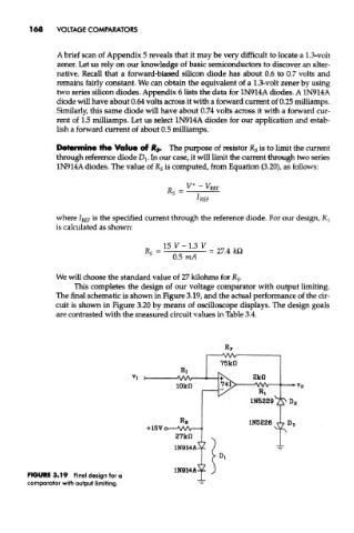
This completes the design of our voltage comparator with output limiting.
The final schematic is shown in Figure 3.19, and the actual performance of the cir-
cuit is shown in Figure 3.20 by means of oscilloscope displays. The design goals
are contrasted with the measured circuit values in Table 3.4.
FIGURE 3.19 Final design for a
comparator with output limiting.