
Page 187 - Op Amps Design, Applications, and Troubleshooting
P. 187
170 VOLTAGE COMPARATORS
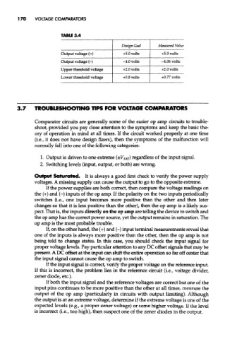
TABLE 3.4
Design Goal Measured Value
Output voltage (+) + 5.0 volts +5.0 volts
Output voltage (-) -4,0 volts -4.06 volts
Upper threshold voltage +2.0 volts +2.0 volts
Lower threshold voltage +0.8 volts +0.77 volts
3.7 TROUBLESHOOTING TIPS FOR VOLTAGE COMPARATORS
Comparator circuits are generally some of the easier op amp circuits to trouble-
shoot, provided you pay close attention to the symptoms and keep the bask the-
ory of operation in mind at all times. If the circuit worked properly at one time
(i.e., it does not have design flaws), then the symptoms of the malfunction will
normally fall into one of the following categories:
1. Output is driven to one extreme (±V SAr) regardless of the input signal.
2. Switching levels (input, output, or both) are wrong.
Output Saturated. It is always a good first check to verify the power supply
voltages. A missing supply can cause the output to go to the opposite extreme.
If the power supplies are both correct, then compare the voltage readings on
the (+) and (-) inputs of the op amp. If the polarity on the two inputs periodically
switches (i.e., one input becomes more positive than the other and then later
changes so that it is less positive than the other), then the op amp is a likely sus-
pect. That is, the inputs directly on the op amp are telling the device to switch and
the op amp has the correct power source, yet the output remains in saturation. The
op amp is the most probable trouble.
If, on the other hand, the (+) and (-) input terminal measurements reveal that
one of the inputs is always more positive than the other, then the op amp is not
being told to change states. In this case, you should check the input signal for
proper voltage levels. Pay particular attention to any DC offset signals that may be
present. A DC offset at the input can shift the entire operation so far off center that
the input signal cannot cause the op amp to switch.
If the input signal is correct, verify the proper voltage on the reference input.
If this is incorrect, the problem lies in the reference circuit (i.e., voltage divider,
zener diode, etc.).
If both the input signal and the reference voltages are correct but one of the
input pins continues to be more positive than the other at all times, measure the
output of the op amp (particularly in circuits with output limiting). Although
the output is at an extreme voltage, determine if the extreme voltage is one of the
expected levels (e.g., a proper zener voltage) or some higher voltage. If the level
is incorrect (i.e., too high), then suspect one of the zener diodes in the output.