
Page 19 - Op Amps Design, Applications, and Troubleshooting
P. 19
BASIC CONCEPTS OF THE INTEGRATED OPERATIONAL AMPLIFIER
affected by the voltage on either of its inputs alone, but it is affected by the differ-
ence in voltage between the two inputs. This difference voltage is amplified by the
amplifier and appears in the output in its amplified form. The amplifier may have
a single output, which is referenced to common or ground. If so, it is called a
single-ended amplifier. On the other hand, the output of the amplifier may be
taken between two lines, neither of which is common or ground. In this case, the
amplifier is called a double-ended or differential output amplifier.
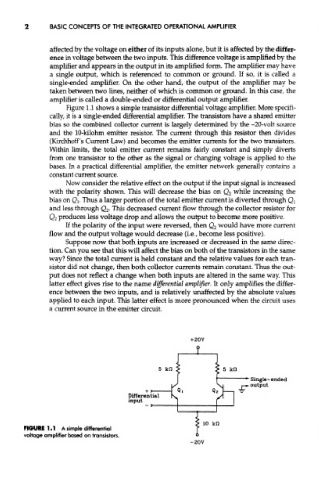
Figure 1.1 shows a simple transistor differential voltage amplifier. More specifi-
cally, it is a single-ended differential amplifier. The transistors have a shared emitter
bias so the combined collector current is largely determined by the -20-volt source
and the 10-kilohm emitter resistor. The current through this resistor then divides
(Kirchhoff's Current Law) and becomes the emitter currents for the two transistors.
Within limits, the total emitter current remains fairly constant and simply diverts
from one transistor to the other as the signal or changing voltage is applied to the
bases. In a practical differential amplifier, the emitter network generally contains a
constant current source.
Now consider the relative effect on the output if the input signal is increased
with the polarity shown. This will decrease the bias on Q 2 while increasing the
bias on Q t. Thus a larger portion of the total emitter current is diverted through Q l
and less through Q 2. This decreased current flow through the collector resistor for
Q 2 produces less voltage drop and allows the output to become more positive.
If the polarity of the input were reversed, then Q 2 would have more current
flow and the output voltage would decrease (i.e., become less positive).
Suppose now that both inputs are increased or decreased in the same direc-
tion. Can you see that this will affect the bias on both of the transistors in the same
way? Since the total current is held constant and the relative values for each tran-
sistor did not change, then both collector currents remain constant. Thus the out-
put does not reflect a change when both inputs are altered in the same way. This
latter effect gives rise to the name differential amplifier. It only amplifies the differ-
ence between the two inputs, and is relatively unaffected by the absolute values
applied to each input. This latter effect is more pronounced when the circuit uses
a current source in the emitter circuit.
FIGURE 1.1 A simple differential
voltage amplifier based on transistors.
-20V