
Page 20 - Op Amps Design, Applications, and Troubleshooting
P. 20
Overview of Operational Amplifiers 3
In certain applications, one of the differential inputs is connected to ground
and the signal to be amplified is applied directly to the remaining input. In this
case the amplifier still responds to the difference between the two inputs, but the
output will be in or out of phase with the input signal depending on which input
is grounded. If the signal is applied to the (+) input with the (-) input grounded,
as labeled in Figure 1.1, then the output signal is essentially in phase with the
input signal. If, on the other hand, the (+) input is grounded and the input signal
is applied to the (-) input, then the output is essentially 180 degrees out of phase
with the input signal. Because of the behavior described, the (-) and (+) inputs are
called the inverting and noninverting inputs, respectively.
1.1.3 A Quick Look Inside the 1C
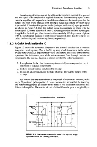
Figure 1.2 shows the schematic diagram of the internal circuitry for a common
integrated circuit op amp. This is the 741 op amp which is common in the indus-
try. It is not particularly important for you to understand the details of the internal
operation. Nor is it worth your while to trace current flow through the internal
components. The internal diagram is shown here for the following reasons:
1. To emphasize the fact that the op amp is essentially an encapsulated circuit
composed of familiar components
2. To show the differential inputs on the op amp
3. To gain an understanding of the type of circuit driving the output of the
op amp
You can see that the entire circuit is composed of transistors, resistors, and a
single 30 picofarad (pF) capacitor. A closer examination shows that the inverting
and noninverting inputs go directly to the bases of two transistors connected as a
differential amplifier. The emitter circuit of this differential pair is supplied by a
EQUIVALENT CIRCUIT SCHEMATIC
FIGURE 1.2 The internal schematic for an MCI 741 op amp. (Copy-
right of Motorola, Inc. Used by permisssion.)