
Page 293 - Op Amps Design, Applications, and Troubleshooting
P. 293
Switching Voltage Regulators 275
Our discussion on switching regulators will be limited to the theory of operation.
Although a switching regulator can be designed around an op amp, most are built
using specialized regulator ICs, which not only simplifies the design but generally
improves the overall performance of the regulator circuit. Nevertheless, an under-
standing of the operation of switching regulators is very important to an engineer
or technician working with equipment being designed today, and no discussion of
regulated power supplies would be complete without this understanding.
6.4.1 Principles of Operation
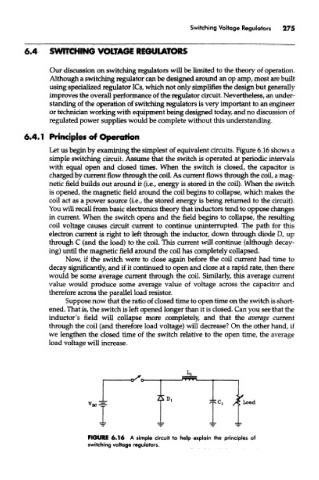
Let us begin by examining the simplest of equivalent circuits. Figure 6.16 shows a
simple switching circuit. Assume that the switch is operated at periodic intervals
with equal open and closed times. When the switch is closed, the capacitor is
charged by current flow through the coil. As current flows through the coil, a mag-
netic field builds out around it (i.e., energy is stored in the coil). When the switch
is opened, the magnetic field around the coil begins to collapse, which makes the
coil act as a power source (i.e., the stored energy is being returned to the circuit).
You will recall from basic electronics theory that inductors tend to oppose changes
in current. When the switch opens and the field begins to collapse, the resulting
coil voltage causes circuit current to continue uninterrupted. The path for this
electron current is right to left through the inductor, down through diode D, up
through C (and the load) to the coil. This current will continue (although decay-
ing) until the magnetic field around the coil has completely collapsed.
Now, if the switch were to close again before the coil current had time to
decay significantly, and if it continued to open and close at a rapid rate, then there
would be some average current through the coil. Similarly, this average current
value would produce some average value of voltage across the capacitor and
therefore across the parallel load resistor.
Suppose now that the ratio of closed time to open time on the switch is short-
ened. That is, the switch is left opened longer than it is closed. Can you see that the
inductor's field will collapse more completely, and that the average current
through the coil (and therefore load voltage) will decrease? On the other hand, if
we lengthen the closed time of the switch relative to the open time, the average
load voltage will increase.
FIGURE 6.16 A simple circuit to help explain the principles of
switching voltage regulators.