
Page 299 - Op Amps Design, Applications, and Troubleshooting
P. 299
280 POWER SUPPLY CIRCUITS
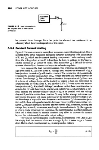
FIGURE 6.18 Load interruption is
the simplest form of over-current
protection.
be protected from damage. Since the protective element has resistance, it can
adversely affect the overall regulation of the circuit.
6.5.2 Constant Current Limiting
Figure 6.19 shows a common example of a constant-current limiting circuit. This is
identical to the series regulators discussed earlier in the chapter with the addition
of RI and Q 2/ which are the current limiting components. Under ordinary condi-
tions, the voltage drop across RI is less than the turn-on voltage for the base-to-
emitter junction of Q 2 (about 0.6 volts). This means that Q 2 is off and the circuit
operates identically to the standard unprotected series regulator.
Now suppose the load current increases. This will cause an increased volt-
age drop across RI. As soon as the R, voltage drop reaches the threshold of Q 2's
base junction, transistor Q 2 will start to conduct. The conduction of Q 2 essentially
bypasses the emitter-base junction of Qi, which prevents any further increase in
current flow through Qj. We can better understand the operation of Q 2 if we view
it in terms of voltage drops. At the instant Q 2 begins to turn on, there must be
approximately 0.6 volts across Rj and another 0.6 to 0.7 volts across the emitter-
base junction of Q^. Kirchhoff's Voltage Law shows us that there must therefore be
about 1.2 to 1.3 volts between the emitter and collector of Q 2 when it starts to con-
duct, because the emitter-collector circuit of Q 2 is in parallel with the voltage
drops of RI and the emitter-base circuit of Qj. Any further attempt to increase cur-
rent beyond this point will cause a decrease in the emitter-collector voltage of Q 2.
As this voltage is in parallel with the series combination of Qi's base-emitter junc-
tion and R], these voltages also tend to decrease. However, if the base-emitter volt-
age of Q! actually decreases, then the emitter current of Qi decreases, causing the
voltage drop across Rj to decrease, resulting in less conduction in Q 2 (the opposite
of what is really occurring). So, in essence, the current reaches a certain maximum
limit and is then forced to remain constant. Any effort to increase the current
beyond this point merely lowers the output voltage.
The value of current required to activate Q 2 is determined with Ohm's Law.
We simply find the amount of current through RI that it takes to get a 0.6-volt
drop. That is, short-circuit current (7 S c) is computed as follows: