
Page 302 - Op Amps Design, Applications, and Troubleshooting
P. 302
282 POWER SUPPLY CIRCUITS
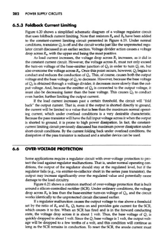
Figure 6.20 shows a simplified schematic diagram of a voltage regulator circuit
that uses foldback current limiting. Note that resistors £4 and R 5 have been added
to the constant-current limiting circuit presented in Figure 6.19. Under normal
conditions, transistor Q 2 is off and the circuit works just like the unprotected regu-
lator circuit discussed in an earlier section. Voltage divider action causes a voltage
drop across R 4/ with the upper end being the most positive.
As load current increases, the voltage drop across RI increases, as it did in
the constant current circuit. However, the voltage across RI must not only exceed
the turn-on voltage of the base-emitter junction of Q 2 in order to turn Q 2 on, but
also overcome the voltage across jR 4. Once this point occurs, however, Q 2 begins to
conduct and reduces the conduction of Qi. This, of course, causes both the output
voltage and the base voltage of Q 2 to decrease. However, because the base voltage
of Q 2 is obtained through a voltage divider, it decreases more slowly than the out-
put voltage. And, because the emitter of Q 2 is connected to the output voltage, it
to
must also be decreasing faster than the base voltage. This causes Q 2 conduct
even harder, further limiting the output current.
If the load current increases past a certain threshold, the circuit will "fold
back" the output current. That is, even if the output is shorted directly to ground,
the current will be limited to a value that is less than the maximum normal operat-
ing current, which under overload conditions is a very desirable characteristic.
Because the pass transistor will have the full input voltage across it when title output
is shorted to ground, it is prone to high power dissipation. In fact, the constant-
current limiting circuit previously discussed has maximum power dissipation under
short-circuit conditions. By the current folding back under overload conditions, the
dissipation of the pass transistor is reduced and a smaller device can be used.
6.6 OVER-VOLTAGE PROTECTION
Some applications require a regulator circuit with over-voltage protection to pro-
tect the load against regulator malfunctions. That is, under normal operating con-
ditions, the output of the regulator should stay at the regulated level, but if the
regulator fails (e.g., via emitter-to-collector short in the series pass transistor), the
output may increase significantly over the regulated value and potentially cause
damage to the load circuitry.
Figure 6.21 shows a common method of over-voltage protection that is built
around a silicon-controlled rectifier (SCR). Under ordinary conditions, the voltage
drop across R 4 is less than the base-emitter turn-on voltage of Q^ and the circuit
works identically to the unprotected circuit discussed earlier.
If a regulator malfunction causes the output voltage to rise above a threshold
set by the ratio of R 4 and R 5, Q 2 turns on and provides gate current for the SCR,
which causes it to fire. When an SCR has fired and is in the forward conducting
state, the voltage drop across it is about 1 volt. Thus, the base voltage of Q l is
quickly dropped to about 1 volt. Since the Q! base voltage is 1 volt, the output volt-
age will be dropped to a few tenths of a volt, and this condition will continue as
long as the SCR remains in conduction. To reset the SCR, the anode current must