
Page 253 - Optical Communications Essentials
P. 253
Performance Measures
Performance Measures 243
power values decrease from left to right. At high received powers the source
noise arising from RIN effects dominates to give a constant CNR. At inter-
mediate levels the shot noise is the main contributor, with a 1-dB drop in CNR
for every 1-dB decrease in received optical power. For low light levels, the thermal
noise of the receiver is the limiting noise term, yielding a 2-dB rolloff in CNR
for each 1-dB drop in received optical power.
It is important to note that the limiting factors can vary significantly depending
on the transmitter and receiver characteristics. For example, for low-impedance
amplifiers the thermal noise of the receiver can be the dominating performance
limiter for all practical link lengths.
14.4. Measuring Performance Parameters
Knowing what is happening at the optical layer of a DWDM link is a critical
issue for network management. The major challenge is how to do real-time
dynamic optical monitoring of each channel in order to gather performance
information for controlling wavelength drifts and power variations.
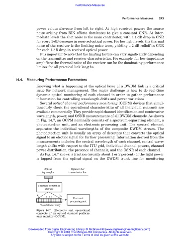
Several optical channel performance monitoring (OCPM) devices that simul-
taneously check the operational characteristics of all individual channels are
available commercially. They provide rapid channel identification and noninvasive
wavelength, power, and OSNR measurements of all DWDM channels. As shown
in Fig. 14.7, an OCPM nominally consists of a spectrum-separating element, a
photodetection unit, and an electronic processing unit. The spectral element
separates the individual wavelengths of the composite DWDM stream. The
photodetection unit is usually an array of detectors that converts the optical
signal to an electric signal for further processing. Information derived from the
measurements includes the central wavelength of each channel, central wave-
length shifts with respect to the ITU grid, individual channel powers, channel
power distribution, the presence of channels, and the OSNR of each channel.
As Fig. 14.7 shows, a fraction (usually about 1 or 2 percent) of the light power
is tapped from the optical signal on the DWDM trunk line for monitoring
Optical Optical fiber
tap coupler transmission line
Spectrum-separating
Spectrum-separating
element
element
• • •
λ 1 λ N
Electronic
Electronic
processing unit
processing unit
Photodetector array
Figure 14.7. Elements and operational
concepts of an optical channel perform-
ance monitor (OCPM).
Downloaded from Digital Engineering Library @ McGraw-Hill (www.digitalengineeringlibrary.com)
Copyright © 2004 The McGraw-Hill Companies. All rights reserved.
Any use is subject to the Terms of Use as given at the website.