
Page 248 - Optical Communications Essentials
P. 248
Performance Measures
238 Chapter Fourteen
be used in the design and installation of networks as well as to check the health
and status of individual optical channels.
In a transmission link consisting of a chain of optical amplifiers, normally the
ASE noise from the optical amplifier dominates, so that one can neglect the
receiver thermal noise and the shot noise. For that case the parameter Q is
related to the OSNR by the expression
2 B o/ B e OSNR
Q (14.7)
1 1 4(OSNR)
Here B o is the bandwidth of an optical bandpass filter in front of the receiver
and B e is the electrical noise-equivalent bandwidth in the receiver.
As an example, consider a 2.5-Gbps system where one needs Q 7 for
BER 10 12 . For this system let the electrical bandwidth B e 2GHz, since
for a bit rate of B bps a receiver bandwidth of at least B e B/2Hz is required.
Furthermore, let the optical filter that is placed at the receiver have a band-
width B o 32GHz. In this case the required OSNR is 4.81 or 6.8dB. However,
there are still a number of other signal degradation effects such as chromatic
dispersion, polarization mode dispersion, and various nonlinear processes that
impose a higher OSNR requirement on the system. For practical purposes, in
the design of an optical system containing a chain of amplifiers, engineers
assume that an OSNR of at least 20dB is needed at the receiver to compen-
sate for these signal impairments.
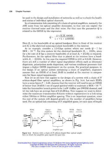
Now let us see how this applies to the design of a system with a chain of N
erbium-doped fiber optical amplifiers, as shown in Fig. 14.4. Let each EDFA
have a noise figure F 5dB. Assume that the receiver will need to see an OSNR
of better than 20dB/0.1nm of signal spectral width to maintain a BER 10 12 ,
take the transmitter launch power to be 1mW (0dBm) per DWDM channel, and
let the link have an average loss of 0.25dB/km. Now suppose we want to deter-
mine the maximum transmission distance without regenerators in a link using
either 100-km or 50-km amplifier spacing. This is an important question, since
the cost of the system will depend greatly on the number of amplifiers being
used. For an optical link consisting of N amplified spans, let each span of length
WDM Optical Fiber WDM Optical
mux amplifiers (loss L) demux receivers
(gain G = L)
1-mW
(0-dBm) • • •
inputs
Amplifier span
Figure 14.4. System with a chain of N erbium-doped fiber optical ampli-
fiers in which the amplifier gain equals the span loss.
Downloaded from Digital Engineering Library @ McGraw-Hill (www.digitalengineeringlibrary.com)
Copyright © 2004 The McGraw-Hill Companies. All rights reserved.
Any use is subject to the Terms of Use as given at the website.