
Page 259 - Optical Communications Essentials
P. 259
Performance Impairments
Performance Impairments 249
have an 0.1-nm spectral width. Consequently each wavelength within an opti-
cal pulse will see a slightly different refractive index and therefore will travel at
a slightly different speed through the fiber (recall from Chap. 3 that light speed
s c/n). Therefore the range of arrival times at the fiber end of the spectrum
of wavelengths will lead to pulse spreading. This effect is known as material
dispersion.
Another dispersion factor is waveguide dispersion. This occurs because the
various frequency components of a pulse travel with slightly different group
velocities in a fiber, and thus arrive at different times at the fiber end.
The combination of these two factors is called chromatic dispersion. This often
is referred to simply as dispersion, since it has a strong impact on the design of
single-mode fiber transmission links. Chromatic dispersion is a fixed quantity
at a specific wavelength and is measured in units of picoseconds per kilometer
of fiber per nanometer of optical source spectral width, that is, it is measured
in ps/(km nm). For example, a single-mode fiber might have a chromatic dis-
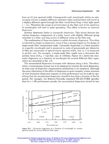
persion value of D CD 2ps/(km nm) at 1550nm. Figure 15.1 shows the chro-
matic dispersion as a function of wavelength for several different fiber types,
which are described in Sec. 4.8.
The accumulated dispersion increases with distance along a link. Therefore,
either a transmission system has to be designed to tolerate the total dispersion,
or some type of dispersion compensation method has to be employed. Although
the exact calculation of the effect of dispersion is quite complex, a basic estimate
of what limitation dispersion imposes on link performance can be made by spe-
cifying that the accumulated dispersion should be less than a fraction of the bit
period. For example, the Bellcore/Telcordia standard GR-253-CORE specifies
that for a 1-dB performance penalty the accumulated dispersion should be less
20
G.655b
G.652
Dispersion [ps/(nm . km)] 0 G.655
10
-10 G.653
S-Band C-Band L-Band
1450 1480 1510 1540 1570 1600 163
Wavelength (nm)
Figure 15.1. Chromatic dispersion as a function of wavelength in various
spectral bands for several different fiber types.
Downloaded from Digital Engineering Library @ McGraw-Hill (www.digitalengineeringlibrary.com)
Copyright © 2004 The McGraw-Hill Companies. All rights reserved.
Any use is subject to the Terms of Use as given at the website.