
Page 261 - Optical Communications Essentials
P. 261
Performance Impairments
Performance Impairments 251
DCF DCF DCF DCF
Accumulated dispersion Dispersion shift due to DCF L Accumulated dispersion Dispersion accumulation L
in transmission fiber
Fiber loss Power loss Fiber loss
Optical power Optical power Power loss
in DCF
L in DCF L
(a) Precompensation (b) Postcompensation
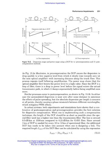
Figure 15.2. Dispersion maps and power maps using a DCF for (a) precompensation and (b) post-
compensation methods.
As Fig. 15.2a illustrates, in precompensation the DCF causes the dispersion to
drop quickly to a low negative level from which it slowly rises towards zero (at
the next optical amplifier) with increasing distance along the trunk fiber. This
process repeats itself following amplification. The power map shows that the
optical amplifier first boosts the power level to a high value. Since the DCF is a
loop of fiber, there is a drop in power level before the signal enters the actual
transmission path, in which it decays exponentially before being amplified once
more.
Similar processes occur in postcompensation, as shown in Fig. 15.2b. In either
case the accumulated dispersion is near zero after some distance to minimize
the effects of pulse spreading, but the absolute dispersion per length is nonzero
at all points, thereby causing a phase mismatch between different wavelengths,
which mitigates FWM effects.
In actual systems, both experiments and simulations have shown that a com-
bination of postcompensation and precompensation provides the best solution
for dispersion compensation. When one is implementing such a compensation
technique, the length of the DCF should be as short as possible since the spe-
cial fiber used has a higher loss than the transmission fiber. The loss is around
0.5dB/km at 1550nm compared to 0.21dB/km for G.655 fiber. Since around
1km of DCF is needed for every 10 to 12km of operational fiber, the additional
DCF loss needs to be taken into account when one is designing a link. The
required length L DCF of the DCF fiber can be calculated by using the expression
L DCF D TX /D DCF L (15.2)
Downloaded from Digital Engineering Library @ McGraw-Hill (www.digitalengineeringlibrary.com)
Copyright © 2004 The McGraw-Hill Companies. All rights reserved.
Any use is subject to the Terms of Use as given at the website.