
Page 36 - Optical Communications Essentials
P. 36
Optical Communication Systems Overview
26 Chapter Two
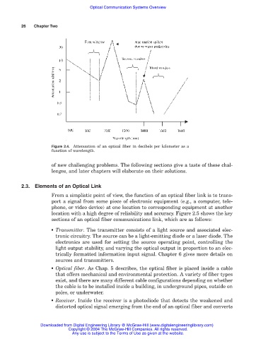
Figure 2.4. Attenuation of an optical fiber in decibels per kilometer as a
function of wavelength.
of new challenging problems. The following sections give a taste of these chal-
lenges, and later chapters will elaborate on their solutions.
2.3. Elements of an Optical Link
From a simplistic point of view, the function of an optical fiber link is to trans-
port a signal from some piece of electronic equipment (e.g., a computer, tele-
phone, or video device) at one location to corresponding equipment at another
location with a high degree of reliability and accuracy. Figure 2.5 shows the key
sections of an optical fiber communications link, which are as follows:
■ Transmitter. The transmitter consists of a light source and associated elec-
tronic circuitry. The source can be a light-emitting diode or a laser diode. The
electronics are used for setting the source operating point, controlling the
light output stability, and varying the optical output in proportion to an elec-
trically formatted information input signal. Chapter 6 gives more details on
sources and transmitters.
■ Optical fiber. As Chap. 5 describes, the optical fiber is placed inside a cable
that offers mechanical and environmental protection. A variety of fiber types
exist, and there are many different cable configurations depending on whether
the cable is to be installed inside a building, in underground pipes, outside on
poles, or underwater.
■ Receiver. Inside the receiver is a photodiode that detects the weakened and
distorted optical signal emerging from the end of an optical fiber and converts
Downloaded from Digital Engineering Library @ McGraw-Hill (www.digitalengineeringlibrary.com)
Copyright © 2004 The McGraw-Hill Companies. All rights reserved.
Any use is subject to the Terms of Use as given at the website.