
Page 38 - Optical Communications Essentials
P. 38
Optical Communication Systems Overview
28 Chapter Two
■ Active components. Lasers and optical amplifiers fall into the category of active
devices, which require an electronic control for their operation. Not shown in
Fig. 2.5 are a wide range of other active optical components. These include
light signal modulators, tunable (wavelength-selectable) optical filters, vari-
able optical attenuators, and optical switches. Chapter 10 gives the details of
these devices.
2.4. WDM Concept
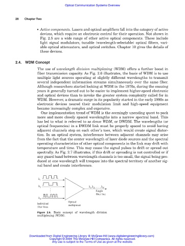
The use of wavelength division multiplexing (WDM) offers a further boost in
fiber transmission capacity. As Fig. 2.6 illustrates, the basis of WDM is to use
multiple light sources operating at slightly different wavelengths to transmit
several independent information streams simultaneously over the same fiber.
Although researchers started looking at WDM in the 1970s, during the ensuing
years it generally turned out to be easier to implement higher-speed electronic
and optical devices than to invoke the greater system complexity called for in
WDM. However, a dramatic surge in its popularity started in the early 1990s as
electronic devices neared their modulation limit and high-speed equipment
became increasingly complex and expensive.
One implementation trend of WDM is the seemingly unending quest to pack
more and more closely spaced wavelengths into a narrow spectral band. This
has led to what is referred to as dense WDM, or DWDM. The wavelengths (or
optical frequencies) in a DWDM link must be properly spaced to avoid having
adjacent channels step on each other’s toes, which would create signal distor-
tion. In an optical system, interference between adjacent channels may arise
from the fact that the center wavelength of laser diode sources and the spectral
operating characteristics of other optical components in the link may drift with
temperature and time. This may cause the signal pulses to drift or spread out
spectrally. As Fig. 2.7 illustrates, if this drift or spreading is not controlled or if
any guard band between wavelength channels is too small, the signal being pro-
duced at one wavelength will trespass into the spectral territory of another sig-
nal band and create interference.
λ 1
λ 2
λ 1 ,λ 2 , . . . , λ N
Single
fiber line
λ N
Optical
Individual
multiplexer
fiber lines
Figure 2.6. Basic concept of wavelength division
multiplexing (WDM).
Downloaded from Digital Engineering Library @ McGraw-Hill (www.digitalengineeringlibrary.com)
Copyright © 2004 The McGraw-Hill Companies. All rights reserved.
Any use is subject to the Terms of Use as given at the website.