
Page 48 - Optical Communications Essentials
P. 48
The Behavior of Light
38 Chapter Three
a pressure of 760 torr and 15°C is
8 2,406,030 15,997
.
n air 1 10+ 8342 13 130 1/λ 2 38.9 1/λ 2 (3.5)
where the wavelength λ of the light is measured in micrometers (10 6 m). Using this
equation, we find that for a wavelength of 1550nm 1.550µm used in fiber optic
communications, the refractive index for air is n air 1.00027325, which yields a speed
of light c air 299,710,562m/s.
3.5. Reflection and Refraction
The concepts of reflection and refraction can be understood most easily by using
light rays. When a light ray encounters a boundary separating two materials
that have different refractive indices, part of the ray is reflected to the first
medium and the remainder is bent (or refracted) as it enters the second mate-
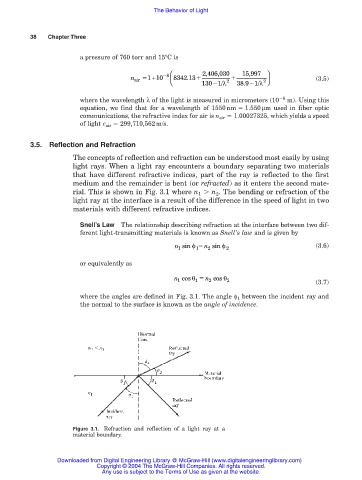
rial. This is shown in Fig. 3.1 where n 1 n 2 . The bending or refraction of the
light ray at the interface is a result of the difference in the speed of light in two
materials with different refractive indices.
Snell’s Law The relationship describing refraction at the interface between two dif-
ferent light-transmitting materials is known as Snell’s law and is given by
n sin φ n sin φ 2 (3.6)
2
1
1
or equivalently as
n cos θ n cos θ 2 (3.7)
1
1
2
where the angles are defined in Fig. 3.1. The angle φ 1 between the incident ray and
the normal to the surface is known as the angle of incidence.
Figure 3.1. Refraction and reflection of a light ray at a
material boundary.
Downloaded from Digital Engineering Library @ McGraw-Hill (www.digitalengineeringlibrary.com)
Copyright © 2004 The McGraw-Hill Companies. All rights reserved.
Any use is subject to the Terms of Use as given at the website.