
Page 111 - Optical Switching And Networking Handbook
P. 111
05_200023_CH04/Batesx 1/17/01 8:18 AM Page 96
96 Chapter 4
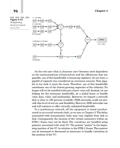
T1- 1.544 Mbps
Figure 4-10
C-11 VC-11 TU-11
Multiplexing E1- 2.048 Mbps x 4
structure based C-12 VC-12 TU-12 x 3 TUG- VC-3 AU-3
on G.707 x 1 2 x 7 x 3
C-2 VC-2 TU-2
T2- 6.312 Mbps x 7
STM-N
34.368 Mbps/ 44.736 Mbps AUG
C-3 VC-3 TU-3 x 1 TUG- 155 x n Mbps
3
x 3 x 1
C-4 VC-4 x 1 AU-4
TEAMFLY
139.368 Mbps
As the end user (that is, business user) becomes more dependent
on the communications infrastructure and the efficiencies that are
possible, use of this bandwidth is becoming explosive. At one time, a
gigabit of capacity was considered an enormous amount. Now, giga-
bit to the desk is more the norm. Therefore, use of this bandwidth
constitutes one of the fastest-growing segments of the industry. No
longer will we be satisfied with just a basic voice call. Instead, we are
looking for the necessary bandwidth, on a global basis, to handle
voice, data, video, and multimedia. Moreover, we require a network
that is close to 100 percent available. PDH networks could not pro-
vide this level of service and flexibility. However, SDH networks can
and will continue to offer virtually unlimited bandwidth.
In a synchronous network, all the equipment is timed (synchro-
nized) to an overall network clock, as we saw in Chapter 3.The delay
associated with transmission links may vary slightly from link to
link. Consequently, the location of the virtual containers within an
STM-1 frame may not be fixed. The variations are handled using
pointers associated with each VC. The pointer “points” to the begin-
ning position of the VC in relation to the STM-1 frame. This pointer
can be increased or decreased as necessary to handle variations in
the position of the VC.
®
Team-Fly