
Page 36 - Optical Switching And Networking Handbook
P. 36
Introduction to Optical Communications 21
Figure 1-10
Electrical Signal
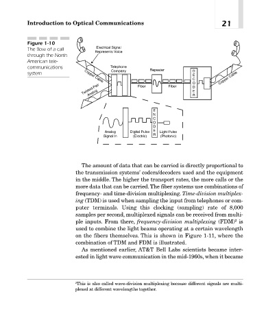
The flow of a call
Represents Voice
through the North
American tele-
communications Telephone
Company Repeater D
system
E
C Copper Cable
Copper Cable
O
Twisted-Pair D
Fiber
Fiber
Analog
E
R
E
N
C
O
D
E
Analog Digital Pulse Light Pulse
Signal In (Electric) R (Photonic)
The amount of data that can be carried is directly proportional to
the transmission systems’ coders/decoders used and the equipment
in the middle. The higher the transport rates, the more calls or the
more data that can be carried.The fiber systems use combinations of
frequency- and time-division multiplexing. Time-division multiplex-
ing (TDM) is used when sampling the input from telephones or com-
puter terminals. Using this clocking (sampling) rate of 8,000
samples per second, multiplexed signals can be received from multi-
2
ple inputs. From there, frequency-division multiplexing (FDM) is
used to combine the light beams operating at a certain wavelength
on the fibers themselves. This is shown in Figure 1-11, where the
combination of TDM and FDM is illustrated.
As mentioned earlier, AT&T Bell Labs scientists became inter-
ested in light wave communication in the mid-1960s, when it became
2 This is also called wave-division multiplexing because different signals are multi-
plexed at different wavelengths together.