
Page 231 - Optofluidics Fundamentals, Devices, and Applications
P. 231
206 Cha pte r Ni ne
Dielectrophoresis presents an alternative mechanism to control
the curvature of fluidic lens. Because of the effect of dielectrophore-
sis, a dielectric molecule experiences a net force in an electrical field
gradient. Reference 24 utilizes this phenomenon to control the curva-
ture of a liquid crystal droplet. Liquid crystals are dielectric mole-
cules, and electrical field gradients can apply forces to the dielectric
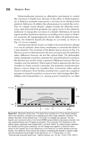
molecules to change the curvature of a droplet. References 25 and 26
report another liquid lens structure consisting of two types of dielec-
tric materials. By manipulating the electric field with patterned elec-
trodes, the dielectric liquid can change its curvature, as shown in
Fig. 9-3, for an example.
Among many fluidic lenses, we believe the most attractive design
is to use an optically clear elastic membrane to constrain the fluid in
a lens chamber. The structure of the fluidic lens is shown in Fig. 9-4.
The lens power is determined by the lens curvature and the refractive
index difference between air and the optical fluid. The deformable
elastic membrane is used to constrain the optical fluid and to produce
the desired lens profile under a pressure difference between the lens
chamber and the ambient. When optical fluid is injected into the lens
chamber to create a positive pressure, the elastomer membrane pro-
duces a convex shape for a positive lens. Conversely, when optical
fluid is withdrawn from the lens chamber into a reservoir, a negative
pressure is formed to produce a concave lens. Such design offers flex-
ibilities and characteristics (i.e., tuning power) matched by no other
Glass
0.5 mm
High dielectric liquid
3 mm
ITO electrodes Dielectric forces
Æ
Low dielectric liquid E
1 μm
3 mm Teflon
FIGURE 9-3 Dielectric fl uidic lens. The liquid lens consists of a 15 μL (liquid) droplet
with a low dielectric constant and a sealing liquid with a high dielectric constant. The
bottom diameter of the droplet was 7 mm when no voltage was applied. The two
liquids were injected inside a 3-mm-thick PMMA (polymethylmethacrylate) chamber that
was sealed between two ITO glass substrates. The concentric ITO electrods on the
®
bottom glass substrate were coated with 1-μm-thick Tefl on to reduce friction between
the droplet and the glass substrate. As the voltage was applied, a dielectric force
arose on the droplet due to the difference in the dielectric constant between the two
liquids. The dielectric force shrunk the droplet, increasing the droplet’s contact angle
and shortening the focal length of the liquid lens. (C. C. Cheng and J. A. Yeh,
“Dielectrically actuated liquid lens,” Optics Express, vol. 15, pp. 7140–7145, 2007.)